Modular snake-like robot joint

A snake-like robot, modular technology, applied in manipulators, program-controlled manipulators, manufacturing tools, etc., can solve the problems of poor position stabilization, large reverse backlash, long control cycle, etc., to achieve short control cycle, reverse The effect of small clearance and long service life

Active Publication Date: 2017-09-19
HARBIN INST OF TECH
View PDF9 Cites 7 Cited by
  • Summary
  • Abstract
  • Description
  • Claims
  • Application Information

AI Technical Summary

Problems solved by technology

[0004] The purpose of the present invention is to provide a modular snake-like robot joint to solve the problem of large reverse backlash, long control period, low precision and stable position due to the combination of steering gear drive and gear transmission in the existing snake-like joints. The problem of poor ability

Method used


Image

  • Modular snake-like robot joint
  • Modular snake-like robot joint
  • Modular snake-like robot joint

Examples


specific Embodiment approach 1

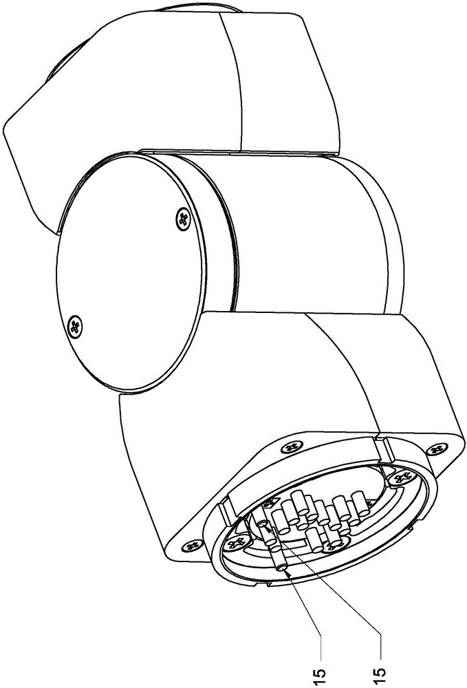
[0027] Specific implementation mode one: combine figure 1 , figure 2 and image 3 Describe this embodiment. This embodiment includes a joint input part, a joint output part, an intermediate shaft joint, a motor assembly and a harmonic reducer. Both ends of the intermediate shaft joint are respectively provided with a joint input part and a joint output part. The motor assembly and the harmonic reducer are arranged side by side inside the intermediate shaft joint. The output end of the motor assembly is connected with the harmonic reducer. The joint is the swing motion of the axis.

[0028] In the present invention, the harmonic reducer drives the joint output part to perform a swing motion centered on the intermediate shaft joint, which means that the harmonic reducer drives the joint output part to perform a swing motion centered on the intermediate shaft joint.

[0029] The intermediate shaft joint of the present invention is a cylindrical shaft joint, figure 2 It is a...

specific Embodiment approach 2

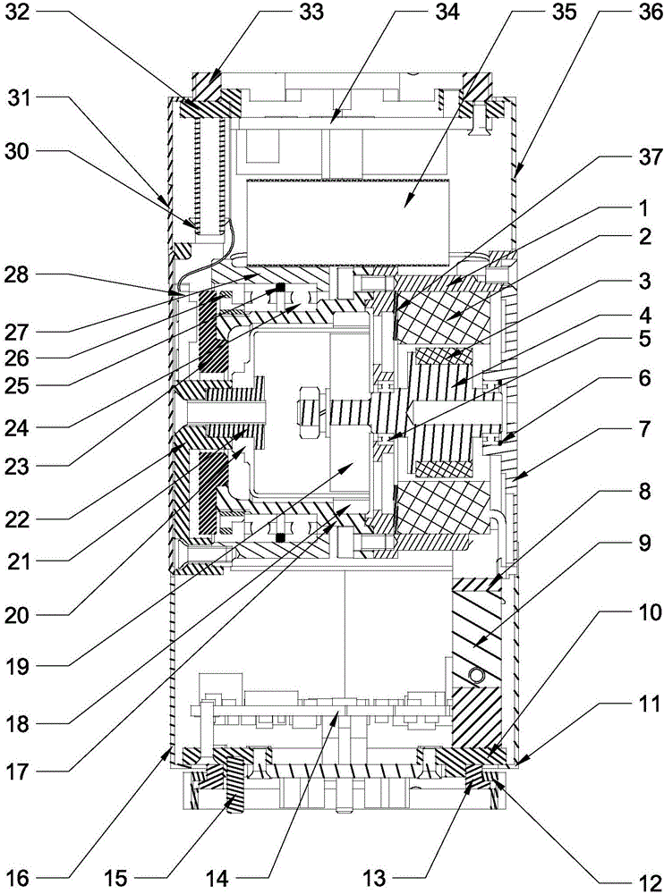
[0031] Specific implementation mode two: combination figure 1 , figure 2 and image 3 Describe this embodiment, in this embodiment, the motor assembly includes a motor housing 1, a motor stator 2, a motor rotor 3, a motor shaft 4 and a motor end cover 7, the motor housing 1 is arranged inside the intermediate shaft joint, and the motor shaft 4 is arranged on the motor The inside of the housing 1 is connected with the motor end cover 7, the motor rotor 3 is sleeved on the motor shaft 4, and the motor stator 2 is sleeved outside the motor rotor 3 and is fixedly installed on the inner wall of the motor housing 1.

[0032] In this embodiment, one end of the motor shaft 4 is connected to the motor casing 1 through the first deep groove ball bearing 5, and the other end of the motor shaft 4 is connected to the motor end cover 7 through the second deep groove ball bearing 5, and the second deep groove A gasket 6 is arranged between the ball bearing 5 and the motor end cover 7 . T...

specific Embodiment approach 3

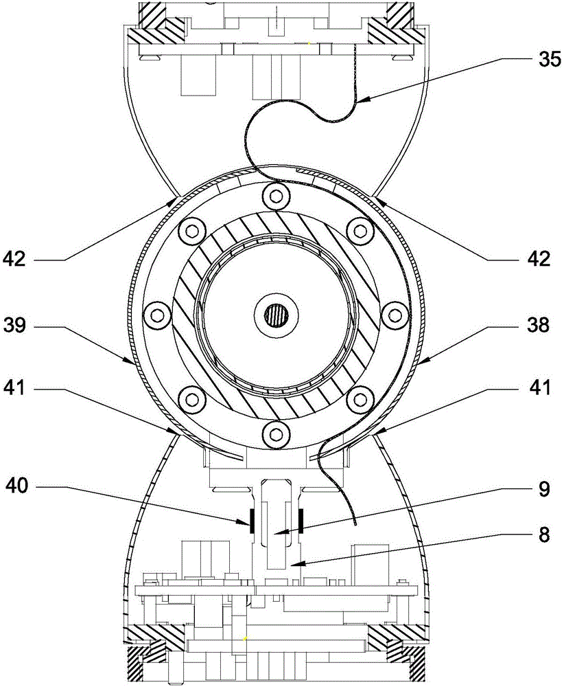
[0034] Specific implementation mode three: combination figure 1 , figure 2 and image 3 Describe this embodiment. In this embodiment, the joint input part includes a torque sensor elastic body 8, an overload protection block 9, a joint input end cover 10, a joint input end first shell 11, a motor drive plate 14, and a joint input end second shell. 16 and two cylindrical pins 15, the first housing 11 of the joint input end and the second housing 16 of the joint input end are detachably connected to the end cover 10 of the joint input end, and a first cavity is formed inside the three, and the torque sensor The elastic body 8, the overload protection block 9 and the motor drive plate 14 are arranged in the first inner cavity, the overload protection block 9 is arranged in the inside of the elastic body 8 of the torque sensor, and one end of the elastic body 8 of the torque sensor is connected with the motor housing 1, and the torque sensor The other end of the elastic body 8 ...


PUM


Abstract

The invention relates to a snake-like robot joint, in particular to a modular snake-like robot joint. The problems that due to combination of a servo driving mode and a gear transmission mode, an existing snake-like joint is large in reverse backlash, long in control period, low in precision and poor in positioning capacity are solved. The modular snake-like robot joint comprises a joint input part, a joint output part, an intermediate shaft section, a motor assembly and a harmonic reducer, wherein the joint input part and the joint output part are arranged at the two ends of the intermediate shaft section correspondingly; the motor assembly and the harmonic reducer are arranged inside the intermediate shaft section side by side; the output end of the motor assembly is connected with the harmonic reducer and drives the harmonic reducer to rotate; and the harmonic reducer drives the joint output part to make swinging motion with the intermediate shaft section as an axis. Through arrangement of a torque sensor and a joint output end position sensor for measuring force-position information of the snake-like robot joint, the perceptive function of a robot is improved, and the robot can be controlled conveniently. The modular snake-like robot joint is applicable to snake-like robots.

Description

technical field [0001] The invention relates to a robot joint and belongs to the field of snake robots. Background technique [0002] Compared with traditional industrial robots, snake-shaped robots have the ability to traverse narrow spaces, overcome obstacles in complex environments such as multiple obstacles, dexterous operation capabilities with super-redundant degrees of freedom, and reconfigurable capabilities in dangerous environments. It has become a hot issue in the field of robot research, and has been paid more and more attention by researchers. Snake robots are commonly used for pipeline inspection, disaster relief, space exploration of planetary surfaces, and other tasks. The most critical research difficulty of the snake-like robot lies in the design of the actuator of the snake-like robot, that is, the joints of the snake-like robot. [0003] According to the query of published patents, it is known that there are many snake-shaped robots driven by steering g...

Claims


Application Information

Patent Timeline
Patent Type & Authority Applications(China)
IPC IPC(8): B25J17/00B25J9/06
CPCB25J9/065B25J17/00
Inventor 孙永军朱映远史士财倪风雷周云虎刘伊威刘宏
Owner HARBIN INST OF TECH
Why Eureka
Try Eureka