A Modular Snake Robot Joint
A snake-like robot, modular technology, applied in manipulators, program-controlled manipulators, manufacturing tools, etc., can solve the problems of poor position stability, large reverse backlash, long control cycle, etc., to achieve short control cycle, reverse The effect of small clearance and long service life
- Summary
- Abstract
- Description
- Claims
- Application Information
AI Technical Summary
Problems solved by technology
Method used
Image
Examples
specific Embodiment approach 1
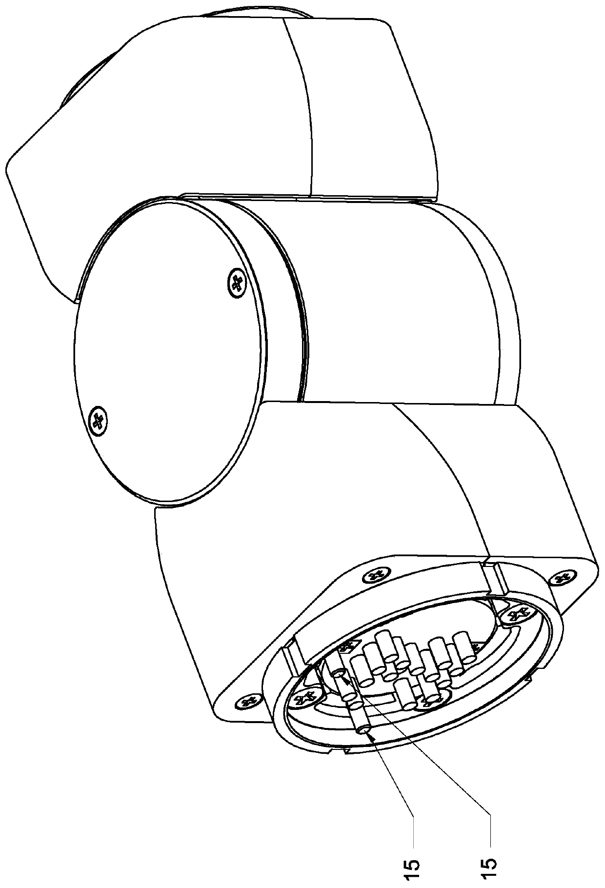
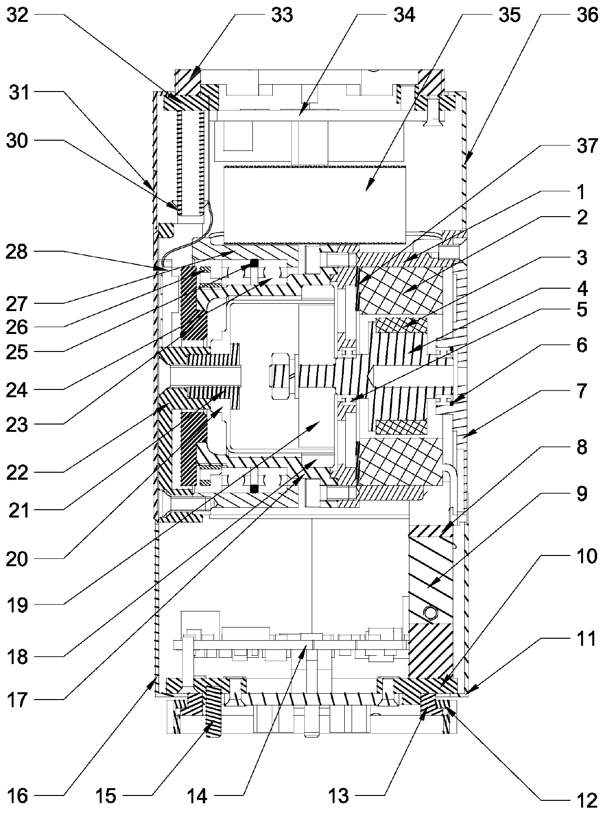
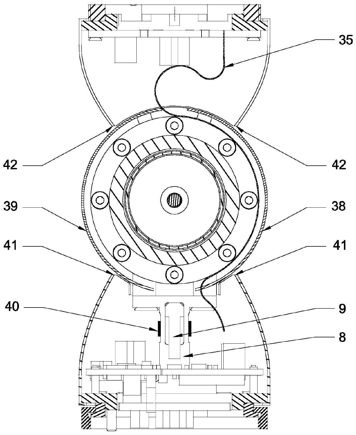
[0027] Specific implementation mode one: combine figure 1 , figure 2 and image 3 Describe this embodiment. This embodiment includes a joint input part, a joint output part, an intermediate shaft joint, a motor assembly and a harmonic reducer. Both ends of the intermediate shaft joint are respectively provided with a joint input part and a joint output part. The motor assembly and the harmonic reducer are arranged side by side inside the intermediate shaft joint. The output end of the motor assembly is connected with the harmonic reducer. The joint is the swing motion of the axis.
[0028] In the present invention, the harmonic reducer drives the joint output part to perform a swing motion centered on the intermediate shaft joint, which means that the harmonic reducer drives the joint output part to perform a swing motion centered on the intermediate shaft joint.
[0029] The intermediate shaft joint of the present invention is a cylindrical shaft joint, figure 2 It is a...
specific Embodiment approach 2
[0031] Specific implementation mode two: combination figure 1 , figure 2 and image 3 Describe this embodiment, in this embodiment, the motor assembly includes a motor housing 1, a motor stator 2, a motor rotor 3, a motor shaft 4 and a motor end cover 7, the motor housing 1 is arranged inside the intermediate shaft joint, and the motor shaft 4 is arranged on the motor The inside of the housing 1 is connected with the motor end cover 7, the motor rotor 3 is sleeved on the motor shaft 4, and the motor stator 2 is sleeved outside the motor rotor 3 and is fixedly installed on the inner wall of the motor housing 1.
[0032] In this embodiment, one end of the motor shaft 4 is connected to the motor casing 1 through the first deep groove ball bearing 5, and the other end of the motor shaft 4 is connected to the motor end cover 7 through the second deep groove ball bearing 5, and the second deep groove A gasket 6 is arranged between the ball bearing 5 and the motor end cover 7 . T...
specific Embodiment approach 3
[0034] Specific implementation mode three: combination figure 1 , figure 2 and image 3 Describe this embodiment. In this embodiment, the joint input part includes a torque sensor elastic body 8, an overload protection block 9, a joint input end cover 10, a joint input end first shell 11, a motor drive plate 14, and a joint input end second shell. 16 and two cylindrical pins 15, the first housing 11 of the joint input end and the second housing 16 of the joint input end are detachably connected to the end cover 10 of the joint input end, and a first cavity is formed inside the three, and the torque sensor The elastic body 8, the overload protection block 9 and the motor drive plate 14 are arranged in the first inner cavity, the overload protection block 9 is arranged in the inside of the elastic body 8 of the torque sensor, and one end of the elastic body 8 of the torque sensor is connected with the motor housing 1, and the torque sensor The other end of the elastic body 8 ...
PUM
 Abstract
Description
Claims
Application Information
 - R&D
- Intellectual Property
- Life Sciences
- Materials
- Tech Scout
- Unparalleled Data Quality
- Higher Quality Content
- 60% Fewer Hallucinations
Browse by: Latest US Patents, China's latest patents, Technical Efficacy Thesaurus, Application Domain, Technology Topic, Popular Technical Reports.
© 2025 PatSnap. All rights reserved.Legal|Privacy policy|Modern Slavery Act Transparency Statement|Sitemap|About US| Contact US: help@patsnap.com


