Polished rod sealing device

A polished rod sealer and polished rod technology, which is applied in sealing/packing, engine sealing, wellbore/well parts, etc., can solve the problem of not being able to better seal the wellhead of the pumping well, the lower part cannot be temporarily sealed, and there is no broken rod Blowout prevention and other issues to achieve the effect of avoiding crude oil loss, preventing blowout phenomenon, and reducing eccentric wear of packing

Active Publication Date: 2017-09-19
DONGYING CHANGRUI PETROLEUM MACHINERY PARTS CO LTD
View PDF10 Cites 7 Cited by
  • Summary
  • Abstract
  • Description
  • Claims
  • Application Information

AI Technical Summary

Problems solved by technology

Published a magnetic booster polished rod sealer, application number: 201610372660.1, using a magnetic fluid seal, the actual magnetic fluid seal requires work in a precise dust-free environment, and is not suitable for field production sites in oil fields. At the same time, the magnetic booster polished rod The sealer has the problem of dealing with the upper part, the lower part cannot be temporarily sealed, and it does not have the function of preventing blowout from broken rods
Therefore, the prior art still cannot solve the wellhead sealing, centering, and broken rod blowout prevention problems of pumping wells.

Method used


Image

  • Polished rod sealing device
  • Polished rod sealing device

Examples


Embodiment Construction

[0027] The present invention will be further described below in conjunction with accompanying drawing:

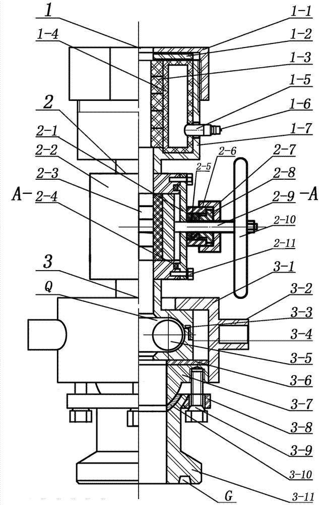
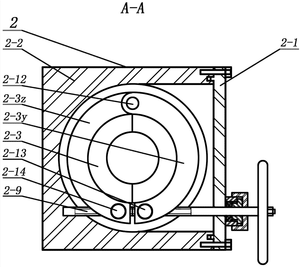
[0028] Such as figure 1 , figure 2 As shown, a polished rod sealer includes: a primary seal assembly 1, a secondary seal assembly 2, and a deflection adjustment blowout prevention assembly 3. It is characterized in that: the main sealing assembly 1 is located at the upper part, the main sealing cavity 1-7 of the main sealing assembly 1 is provided with a main sealing packing 1-3, and a pressure bag 1 is arranged around the main sealing packing 1-3 -4, the lower part of the pressure bag 1-4 is provided with an inlet pipe 1-5, the inlet pipe 1-5 passes through the main sealing chamber 1-7, and the inlet pipe 1-5 is provided with a quick male plug 1 with a check valve -6, the upper part of the main sealing packing 1-3 and the pressure bag 1-4 is provided with a pressing plate 1-2, an upper pressing cap 1-1, and the upper pressing cap 1-1 is threadedly connected with the mai...


PUM


Abstract

Provided is a polished rod sealing device which comprises a main sealing assembly, a secondary sealing assembly and a deviation adjusting and blowout controlling assembly. The polished rod sealing device is characterized in that the main sealing assembly is positioned on the upper portion, the secondary sealing assembly is positioned in the middle portion, and the deviation adjusting and blowout controlling assembly is positioned on the lower portion; when the main sealing assembly is used for achieving normal production of an oil well, a polished rod and a well opening are sealed, the secondary sealing assembly achieves temporary sealing when a main sealing packing is replaced, the lower portion of the deviation adjusting and blowout preventing assembly is connected with the well opening, and the adjustment of angle displacement and horizontal displacement between the polished rod and the well opening is realized, so that the polished rod and the well opening are arranged concentrically, and the function that blowout is prevented after the polished rod is broken is realized. The polished rod sealing device is novel in design and compact in structure, and hydraulic sealing, angle displacement, horizontal displacement and blowout preventing are integrally designed, and the polished rod sealing device can be adjusted and operated conveniently. According to the polished rod sealing device, the eccentric wear of the packing is lightened, the loading of a pumping unit is reduced, and electric energy is saved. By good sealing effectiveness of the packing, the polished rod sealing device is especially applicable to a heavy oil steam injecting area and a heavy oil polymer injecting area for sealing well openings of oil wells, so that crude oil loss is avoided, environmental pollution is prevented and oil filed management level is improved.

Description

technical field [0001] The invention relates to wellhead equipment for pumping wells in oil fields, in particular to a polished rod sealer. Background technique [0002] In the pumping of oil wells, the pumping unit drives the polished rod, sucker rod, and pump to reciprocate up and down to realize oil pumping, and the polished rod reciprocates up and down in the sealer to form a dynamic seal between the packing and the polished rod. In production, due to the installation error of the pumping unit, the foundation of the pumping unit, the sinking of the wellhead pipeline, etc., the suspension point of the pumping unit and the center of the wellhead have angular displacement and horizontal displacement, which makes the wellhead and the polished rod misaligned, resulting in the packing deviation. Grinding, increased load, high energy consumption, seal failure and oil leakage at the wellhead. In addition, due to the long-term operation of the polished rod under the action of alt...

Claims


Application Information

Patent Timeline
Patent Type & Authority Applications(China)
IPC IPC(8): E21B33/03F16J15/40
CPCE21B33/03F16J15/40Y02E10/10
Inventor 高云东乔永生
Owner DONGYING CHANGRUI PETROLEUM MACHINERY PARTS CO LTD
Why Eureka
Try Eureka