Method for forming fidelity-enhanced beam based on distorted towed array

A towed array and beam technology, applied in the field of fidelity-enhanced beamforming based on distorted towed arrays, can solve the problems of unguaranteed global convergence of estimation, huge amount of computation, and unguaranteed unique identification of parameter estimation, etc.

Inactive Publication Date: 2017-09-19
SOUTHEAST UNIV
View PDF0 Cites 26 Cited by
  • Summary
  • Abstract
  • Description
  • Claims
  • Application Information

AI Technical Summary

Problems solved by technology

Self-calibration algorithm Due to the coupling between the position error of the array element and the orientation parameter and some ill-conditioned array structures, the unique identification of the parameter estimation is often not guaranteed. What is more important is the high-dimensional, multi-mode nonlinear optimization corresponding to the joint estimation of the parameters. The problem brings a huge amount of computation, and the estimated global convergence is often not guaranteed

Method used


Image

  • Method for forming fidelity-enhanced beam based on distorted towed array
  • Method for forming fidelity-enhanced beam based on distorted towed array
  • Method for forming fidelity-enhanced beam based on distorted towed array

Examples


Embodiment 1

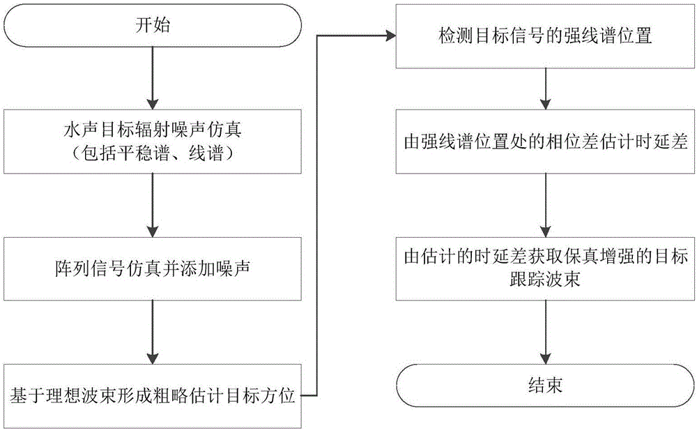
[0120] In this embodiment, the sampling frequency F s =32kHz, the propagation speed v of sound in water is taken as 1500m / s. Using the three-parameter model method to simulate the power spectrum Gxf of the stationary continuum of the radiated noise of underwater acoustic targets, the three parameters are set as follows in the simulation process: ω m =2π×500rad / s, ω c =2π×1000rad / s, λ=0, the signal energy of the stationary continuum σ=1.

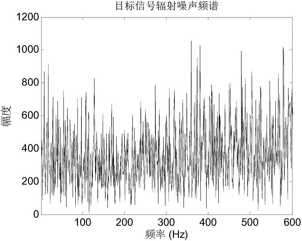
[0121] Simulate the 6 line spectral components of target radiated noise: The energy P of the stationary continuum passing through the line spectral position I And the known signal-to-interference ratio SIR=10, by Obtain the amplitude A of each sinusoidal signal i . The frequency f of the sinusoidal signal i 20Hz, 45Hz, 60Hz, 100Hz, 200Hz, 500Hz respectively. The observation time is T=20s. The target radiation noise signal s(t) is obtained by adding the stationary continuum component and the line spectrum component. The spectrum of...

Embodiment 2

[0129] This embodiment mainly analyzes and verifies the influence of the signal-to-noise ratio on the fidelity-enhanced beamforming disclosed in the present invention. The observation time is T=20s. The data signal-to-noise ratio is from -45dB to -10dB. For each signal-to-noise ratio, the relative error of the magnitude of the estimated beamforming is E, A i Indicates the magnitude of the original data spectrum at the position of the i-th line spectrum, PA i Indicates the magnitude of the estimated beamformed spectrum at the i-th line spectral position. The relative error of the spectrum amplitude of the tracking beamline is used as the performance evaluation index. Such as Figure 7 The schematic diagram of line spectrum reconstruction error changing with signal-to-noise ratio is given. It can be seen from the figure that as the signal-to-noise ratio increases, the reconstruction error based on fidelity-enhanced beamforming gradually becomes smaller; while the beamformi...


PUM


Abstract

The invention discloses a fidelity enhanced beamforming method based on a distorted towed array, comprising the following steps: (1) simulating the radiation noise s(t) of an underwater acoustic target; (2) simulating the observation array signal xi(t), i =1,2,...,M, M is the number of elements in the towed array; (3) Roughly estimate the target orientation based on ideal beamforming as the steering angle when the target signal beam energy is maximum; (4) Detect the L of the target signal The line spectrum position l=1,2,...,L with the largest power; (5) Estimate the average delay difference △τi of each array element in the towed array from the phase difference at the strong line spectrum position, i=1 ,2,...,M; (6) Obtain fidelity-enhanced target tracking beam based on estimated time delay This method uses time delay estimation to correct the influence of distortion of the towed line array on beamforming, and obtain fidelity-enhanced target radiation Noise tracking beam.

Description

technical field [0001] The invention belongs to the field of sonar signal processing, and in particular relates to a fidelity enhanced beamforming method based on a distortion dragged array. Background technique [0002] The current sonar system is mainly divided into hydrophone shore-based array sonar and hydrophone towed line array sonar. Hydrophone towed linear array sonar, referred to as towed array, is an acoustic detection system towed at a certain distance behind the ship's stern. It detects the presence of targets and estimates the presence of targets by receiving the radiated noise or reflected active signals of the navigation target itself. related parameters. It has the characteristics of strong detection ability, low detection frequency, strong hydrological adaptability and no blind spots. The manifold of the hydrophone array is an important parameter of the hydrophone array. When the received signal of the hydrophone array is used for sonar signal processing s...

Claims


Application Information

Patent Timeline
Patent Type & Authority Applications(China)
IPC IPC(8): G01S7/539
CPCG01S7/539
Inventor 武其松徐萍李腾飞罗昕炜方世良
Owner SOUTHEAST UNIV
Why Eureka
Try Eureka