

Buffer circuit and source drive circuit with the buffer circuit
A technology of buffering circuits and circuits, which is applied to static indicators, instruments, etc., to achieve the effect of improving the slew rate
- Summary
- Abstract
- Description
- Claims
- Application Information
AI Technical Summary
Problems solved by technology
Method used
Image

Examples
Embodiment Construction
[0065] Reference will now be made in detail to the exemplary embodiments of the present invention, examples of which are illustrated in the accompanying drawings. In addition, wherever possible, elements / components using the same reference numerals in the drawings and embodiments represent the same or similar parts.
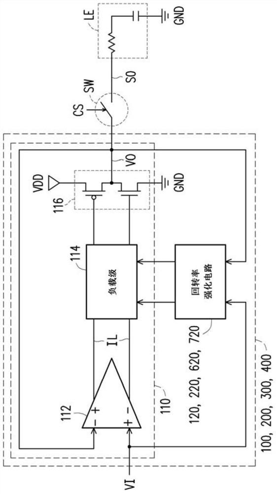
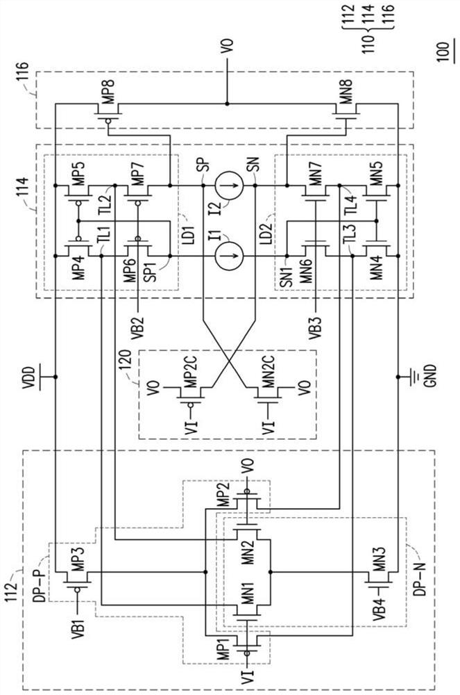
[0066] Please also refer to the following figure 1 and figure 2 , figure 1 It is a schematic circuit block diagram of a buffer circuit with enhanced slew rate shown according to an embodiment of the present invention, figure 2It is a schematic circuit structure diagram of a buffer circuit with enhanced slew rate according to an embodiment of the present invention. The buffer circuit 100 may include an operational amplifier 110 and a slew rate enhancement circuit 120 . Operational amplifier 110 may include an input stage 112 , a load stage 114 , and an output stage 116 . The input stage 112 is used for receiving the input voltage signal VI and the output vo...
PUM
 Abstract
Description
Claims
Application Information