
Plug-in heat dissipation power module

A technology of power module and heat conduction block, applied in electrical components, structural parts of electrical equipment, cooling/ventilation/heating transformation, etc., can solve the problems of waste of cost, low standardization, uneconomical disassembly, etc., to facilitate replacement and maintenance , Efficient heat dissipation effect

Pending Publication Date: 2017-09-19
CHANGZHOU BORI ELECTRIC POWER AUTOMATION EQUIP
View PDF2 Cites 2 Cited by
  • Summary
  • Abstract
  • Description
  • Claims
  • Application Information

AI Technical Summary

Problems solved by technology

For example, the standardization of 1U switch components is relatively low. When a part of the device fails and needs to be repaired and maintained, the entire device needs to be disassembled for replacement. Not only is on-site debugging and maintenance more troublesome, but it also causes a huge waste of cost.
Therefore, it is extremely uneconomical to disassemble the entire device to solve local component failures

Method used


Image

  • Plug-in heat dissipation power module
  • Plug-in heat dissipation power module
  • Plug-in heat dissipation power module

Examples


Embodiment Construction

[0031] The present invention will be further described below in conjunction with the accompanying drawings and given embodiments, but is not limited thereto.

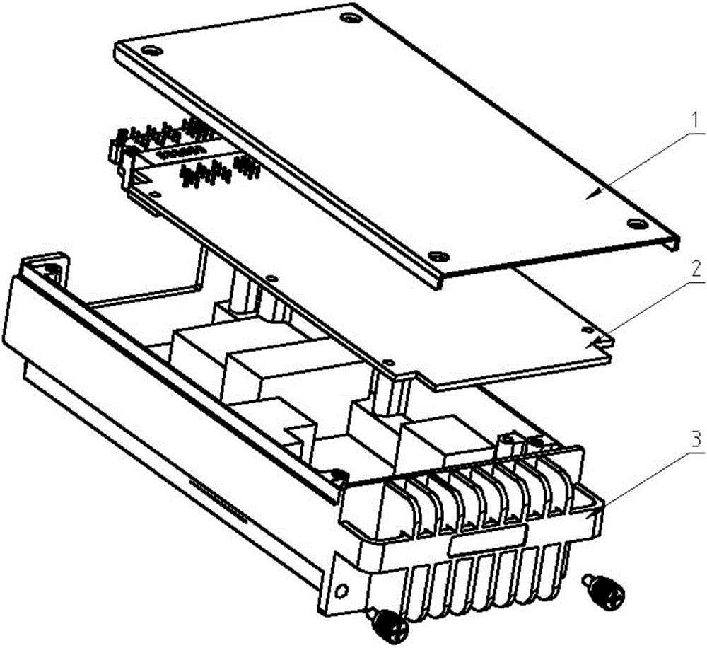
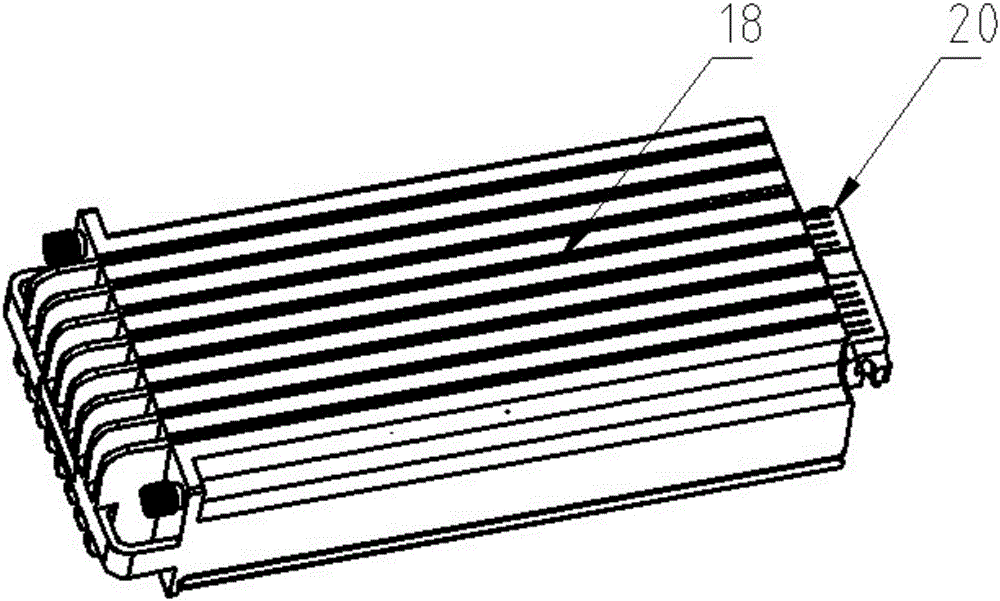
[0032] Such as figure 1 , 2 , 3, 4, 5, 6, 7, and 8, a plug-in heat-dissipating power supply module includes a module cover 1, a PCB board 2 and a module housing assembly 3, and the PCB board 2 and the module The housing assembly 3 is fixedly connected, and the module cover plate 1 is fixedly connected to the module housing assembly 3;

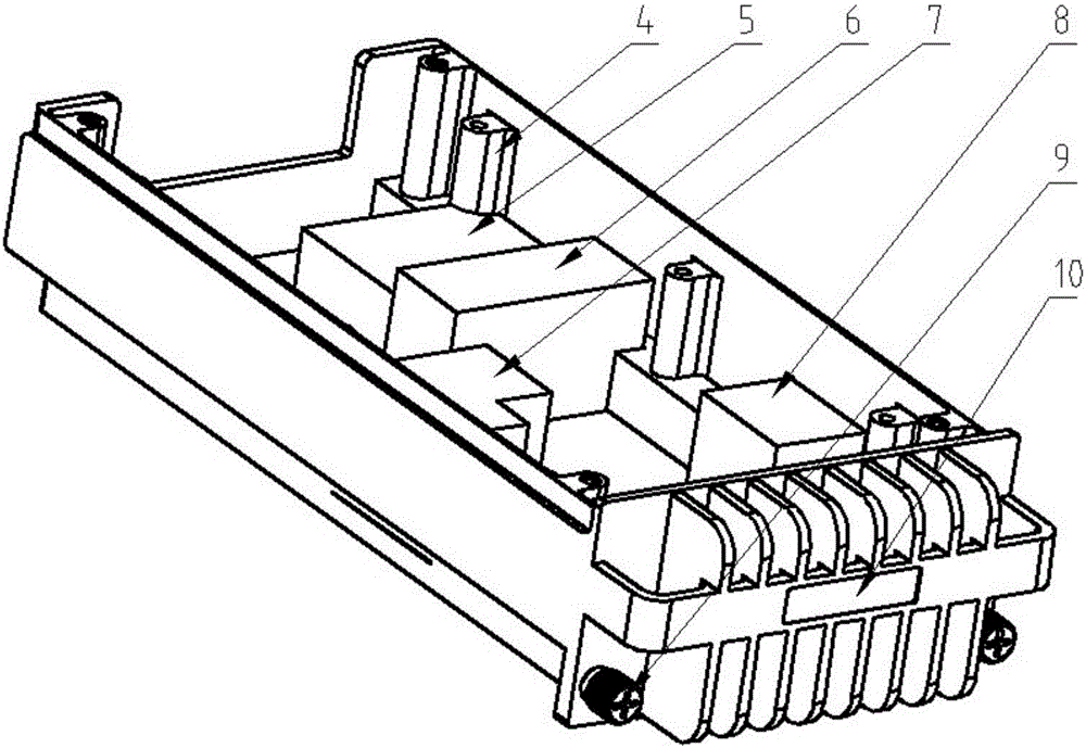
[0033] The module housing assembly 3 includes a module heat dissipation housing 4 and a plurality of heat conducting blocks arranged in the module heat dissipation housing 4 , and the PCB card 2 is arranged above the plurality of heat conducting blocks.

[0034] Such as figure 2 As shown, in order to facilitate the transfer of the heat generated by the heating device on the PCB board 2, and to ensure efficient and reliable thermal conductivity of the heat-conducting copper block, the...


PUM


Abstract

The invention relates to a plug-in heat dissipation power module, the innovations of which are that the plug-in heat dissipation power module comprises a module cover plate, a PCB card and a module housing assembly, the PCB card is fixedly connected with the module housing assembly, and the module cover plate is fixedly connected with the module housing assembly; and the module housing assembly includes a module heat dissipation housing and a plurality of heat conducting blocks disposed in the module heat dissipation housing, and the PCB card is arranged above the plurality of heat conducting blocks. The invention provides a universal power module carrier, which can load a PCB card with various functions to facilitate realization and interchange of the various functions and is suitable for modular application.

Description

technical field [0001] The invention relates to a power supply module, in particular to a plug-in heat-dissipating power supply module, which belongs to the technical field of power electronics. Background technique [0002] Relay protection uses relays with contacts to protect the power system and its components from damage. The relay protection device is a kind of relay protection device that can send a warning signal to the operator on duty in time when the power components in the power system or the power system itself fail to endanger the safe operation of the power system, or directly send a trip command to the controlled circuit breaker to Automated measures and devices to terminate the development of these events. [0003] With the development of relay protection technology, the application of relay protection devices is becoming more and more extensive, and the types are gradually increasing, while the failure rate in use is also increasing year by year. For examp...

Claims


Application Information

Patent Timeline
Patent Type & Authority Applications(China)
IPC IPC(8): H02M1/00H05K7/20
CPCH02M1/00H05K7/20445H05K7/205H05K7/209
Inventor 孟燕菲张国栋邓礼兵李亮柏广枭
Owner CHANGZHOU BORI ELECTRIC POWER AUTOMATION EQUIP
Learn More