Fine type textile fiber grinding and pulping production equipment

A textile fiber and production equipment technology, applied in the field of fine textile fiber grinding and beating production equipment, can solve the problems of rough slurry and low production efficiency, achieve stable quality, high production efficiency, and improve the uniformity of crushing

Inactive Publication Date: 2017-09-22
ZHEJIANG HUANFENG TEXTILE CO LTD
View PDF1 Cites 2 Cited by
  • Summary
  • Abstract
  • Description
  • Claims
  • Application Information

AI Technical Summary

Problems solved by technology

[0005] The purpose of the present invention is to aim at the deficiencies of the prior art, to carry out the pulverization and shearing of the fiber fabric through the rotating centrifugal force, and to screen at the same time, and the screened slurry is formed into a high-quality slurry with a relatively uniform fiber length by grinding and brooming, so as to solve the problem of the prior art. Rough medium slurry and low production efficiency

Method used


Image

  • Fine type textile fiber grinding and pulping production equipment
  • Fine type textile fiber grinding and pulping production equipment
  • Fine type textile fiber grinding and pulping production equipment

Examples


Embodiment 1

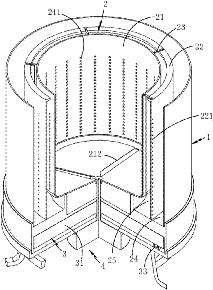
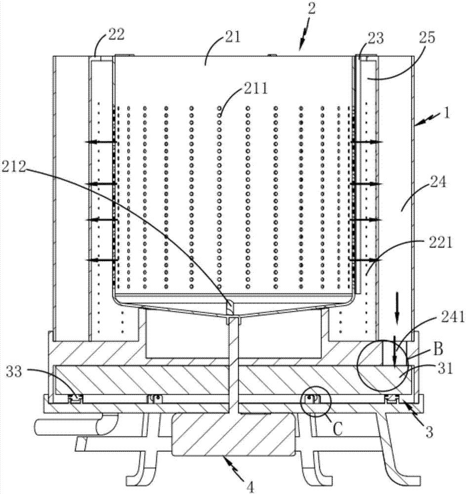
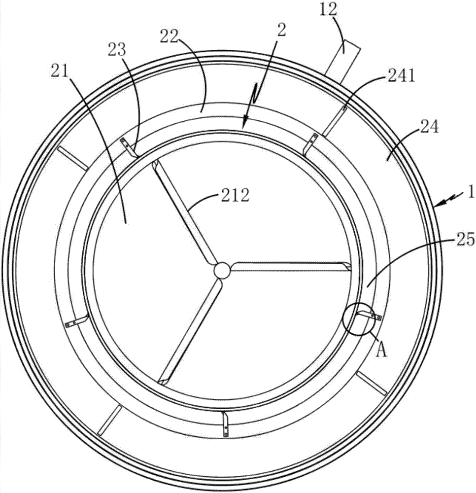
[0034] Such as figure 1 , 2 , 3, 4 and 5, a kind of fine textile fiber grinding and beating production equipment includes a cylindrical beating chamber 1, a crushing mechanism 2 and a grinding mechanism 3, and the crushing mechanism 2 is installed in the inside of the beating chamber 1 , which includes a rotating feed bin 21, a partition 22 fixedly arranged on the periphery of the feed bin 21, and a plurality of partitions fixedly installed on the partition 22 and tangentially matched with the outer circumferential surface of the feed bin 21. A cutter 23, the two sides of the partition plate 22 respectively form a primary separation area 24 and a secondary separation area 25, the rotation of the feed bin 21 drives the material in its internal waters to rotate, and the centrifugal force generated by it On the material, the material is sheared and pulverized by the cutter 23 during the passage of the material along a number of primary screen holes 211 set on the feed bin 21 and...

Embodiment 2

[0036] The inventor believes that in order to better implement the technical solution, further specific implementation methods are necessary, so the inventor describes the second embodiment on the basis of the first embodiment.

[0037] Such as figure 1 , 2 , 3, 4 and 5, a kind of fine textile fiber grinding and beating production equipment includes a cylindrical beating chamber 1, and also includes:

[0038] Pulverizing mechanism 2, described pulverizing mechanism 2 is installed in the inside of described beating chamber 1, and it comprises the feeding bin 21 that is rotatably arranged, the dividing plate 22 that is fixedly arranged on the periphery of this feeding bin 21 and is fixedly installed on this dividing plate 22 A plurality of cutting knives 23 arranged on the top and tangent to the outer circumferential surface of the feed bin 21, the two sides of the partition 22 respectively form a primary partition 24 and a secondary partition 25, the feed bin 21 rotates to dr...


PUM


Abstract

The invention relates to a kind of fine textile fiber grinding and beating production equipment, which includes a cylindrical beating chamber, a crushing mechanism and a grinding mechanism. The crushing mechanism is installed inside the beating chamber, which includes a feeding bin, and a The partition and the cutter fixedly installed on the partition and arranged tangentially with the outer circumferential surface of the feeding bin, the two sides of the partition respectively form a primary separation area and a secondary separation area, and the grinding mechanism is located at the bottom of the crushing mechanism. After being screened by the partition, the materials in the first-level separation area are transferred to the rotating grinding disc along the transfer channel opened at the bottom of the first-level separation area, and the driving assembly fixedly installed at the bottom of the grinding mechanism drives the grinding disc to rotate; through the rotating centrifugal force, the fiber The fabric is crushed and sheared, and screened at the same time, and the screened slurry is broomed to form a high-quality slurry with a relatively uniform fiber length, which solves the problems of rough slurry and low production efficiency in the prior art.

Description

technical field [0001] The invention relates to the field of textile production, in particular to a fine type textile fiber grinding and beating production equipment. Background technique [0002] After the fiber is made into yarn, there are problems of low strength and high hairiness, which cannot meet the technical requirements of weaving. In order to increase the strength of the yarn, reduce the hairiness, and reduce the surface friction of the yarn, it is necessary to use a sizing machine for yarn sizing to improve the quality of the yarn. The weaving requirements of the thread; beating is required to separate the fiber bundles into individual fine fibers, to make the fiber surface fluffy, to make the fibers soft and plastic, or to shorten the long fibers properly. [0003] A textile slurry mixing tank disclosed in Chinese invention patent application number 201510394425.X comprises an outer cylinder with a closed lower end, an inner cylinder with a closed lower end arra...

Claims


Application Information

Patent Timeline
Patent Type & Authority Applications(China)
IPC IPC(8): B02C18/08B02C7/00B02C7/12B02C23/16B02C23/36D06B23/20
CPCB02C18/067B02C7/00B02C7/12B02C18/08B02C23/16B02C23/36B02C2023/165D06B23/205
Inventor 高建良陆恺
Owner ZHEJIANG HUANFENG TEXTILE CO LTD
Why Eureka
Try Eureka