Eureka AIR delivers breakthrough ideas for toughest innovation challenges, trusted by R&D personnel around the world.

MEMS sensor wafer and splitting method of MEMS sensor wafer

A sensor and sensor unit technology, applied in the field of MEMS sensors, can solve the problems of easy damage of silicon film, increase of silicon film breakage rate, reduction of wafer output rate of silicon gauge pressure sensor, etc., so as to improve dicing efficiency, The effect of reducing dust and improving wafer yield

Inactive Publication Date: 2017-09-22
LONGWAY TECH WUXI
View PDF6 Cites 2 Cited by
  • Summary
  • Abstract
  • Description
  • Claims
  • Application Information

AI Technical Summary

Problems solved by technology

[0004] However, since the silicon film of the silicon gauge pressure sensor is very thin, the silicon film is easily damaged by the impact force during the flushing process with coolant, resulting in an increase in the breakage rate of the silicon film and a decrease in the wafer output rate of the silicon gauge pressure sensor

Method used


Image

  • MEMS sensor wafer and splitting method of MEMS sensor wafer
  • MEMS sensor wafer and splitting method of MEMS sensor wafer
  • MEMS sensor wafer and splitting method of MEMS sensor wafer

Examples


Embodiment Construction

[0030] In order to make the object, technical solution and advantages of the present invention clearer, the implementation manner of the present invention will be further described in detail below in conjunction with the accompanying drawings.

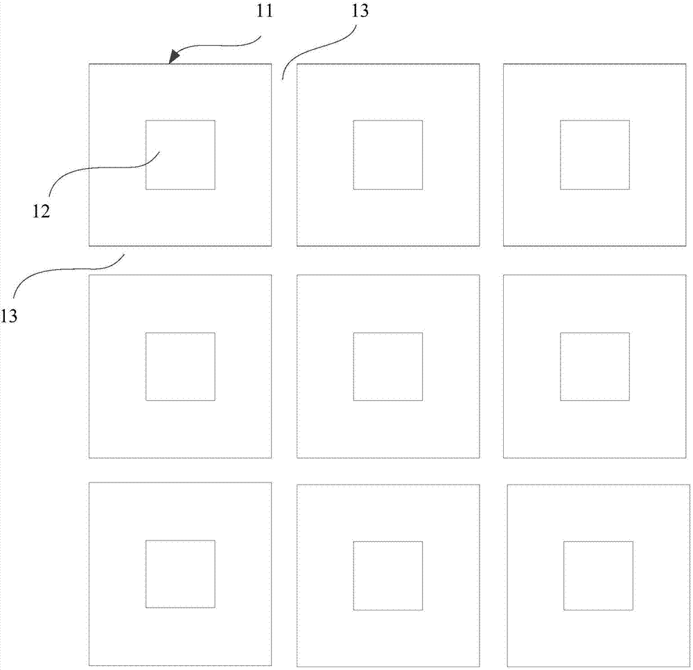
[0031] Please refer to figure 1 , which shows a schematic diagram of a partial structure of a MEMS sensor wafer provided by an exemplary embodiment of the present invention.

[0032] Such as figure 1 As shown, the MEMS (Microelectro Mechanical Systems, Micro Electro Mechanical Systems) sensor wafer includes several MEMS sensor units 11 arranged vertically and horizontally.

[0033] A silicon cup 12 is arranged on the back of each MEMS sensor unit 11, and the location of each silicon cup corresponds to a MEMS sensor structure.

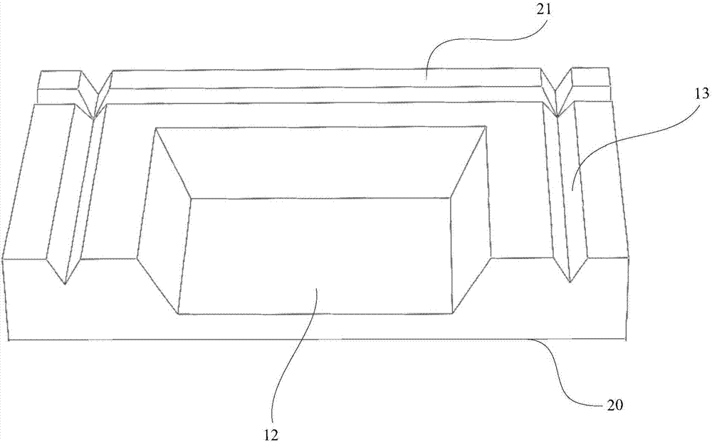
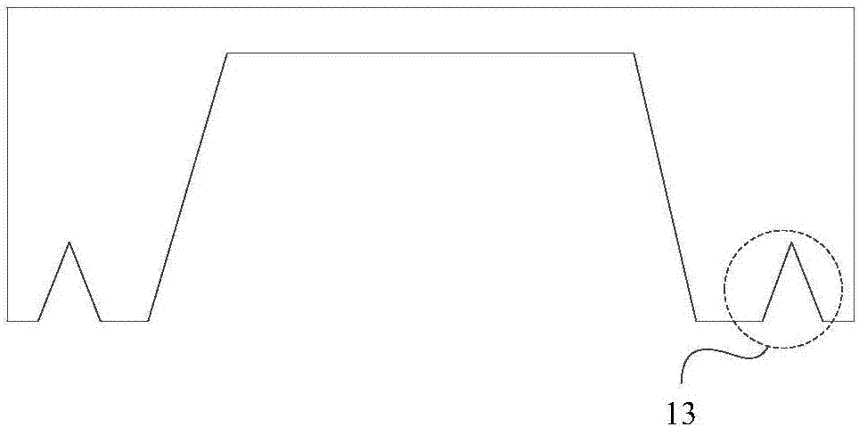
[0034] On the back side of the MEMS sensor wafer, there is a split channel 13 between any two adjacent rows of MEMS sensor units 11 , and there is a split channel 13 between any adjacent two rows of MEMS senso...


PUM


Abstract

The invention discloses a MEMS sensor wafer and a splitting method of the MEMS sensor wafer, belonging to the field of MEMS sensors. The MEMS sensor wafer includes several MEMS sensor units arranged vertically and horizontally; a silicon cup is arranged on the back of each MEMS sensor unit, and the position of each silicon cup corresponds to a MEMS sensor structure; on the back of the MEMS sensor wafer, any There is a split channel between two adjacent rows of MEMS sensor units, and there is a split channel between any two adjacent columns of MEMS sensor units; the section of the split channel is an isosceles triangle, and the base of the isosceles triangle is in line with the MEMS sensor wafer. The surface on the back is on the same plane; it solves the problem that the device structure on the wafer is easily damaged and the wafer output rate is low when mechanical scribing or laser scribing is used; it reduces the dust during scribing and improves the scribing efficiency. and the effect of wafer yield.

Description

technical field [0001] The embodiments of the present invention relate to the field of MEMS sensors, in particular to a MEMS sensor wafer and a splitting method of the MEMS sensor wafer. Background technique [0002] When making the structure of the silicon gauge pressure sensor, it is necessary to perform bulk silicon etching on the silicon wafer to form a silicon cup structure, and form a thin silicon film structure at the bottom of the silicon cup, and make a strain resistance strip on the silicon film to form a sensitive unit , the silicon gauge pressure sensor can use the change of the resistance value of the resistance strip on the silicon membrane under different pressures to calculate the pressure value when it is working. [0003] Since the silicon gauge pressure sensor is manufactured using the overall wafer processing technology, before packaging a single silicon gauge pressure sensor, it is necessary to divide the silicon gauge pressure sensor wafer to obtain a s...

Claims


Application Information

Patent Timeline
IPC IPC(8): B81B7/00B81B7/02B81C99/00
CPCB81B7/02B81B7/0058B81C99/001
Inventor 汪祖民朱恩成
Owner LONGWAY TECH WUXI
Why Eureka
Eureka Blog
Learn More