Constant tool face angle drilling trace control method

A tool face angle and trajectory control technology, which is applied to the automatic control system of drilling, drilling equipment, earthwork drilling and production, etc., can solve the problems of imperfection, single parameter solution method, and lack of universal applicability, so as to facilitate on-site construction, Improved work efficiency, easy matching effect

Inactive Publication Date: 2017-09-22
BC P INC CHINA NAT PETROLEUM CORP +1
View PDF11 Cites 4 Cited by
  • Summary
  • Abstract
  • Description
  • Claims
  • Application Information

AI Technical Summary

Problems solved by technology

However, the existing constant tool face angle model is usually proposed for a specific problem, lacks universal applicability, and has a single parameter solution method
In order to meet the needs of practical engineering applications, the wellbore trajectory model should be versatile and the methods of solving parameters should be diverse. However, the current research in this area is not perfect and systematic, and it is difficult to meet the needs of directional drilling trajectory design and control.

Method used


Image

  • Constant tool face angle drilling trace control method
  • Constant tool face angle drilling trace control method
  • Constant tool face angle drilling trace control method

Examples


Embodiment

[0034] 1. Design model of track with constant tool face angle

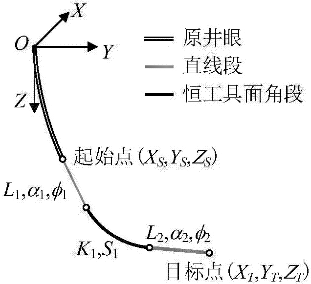
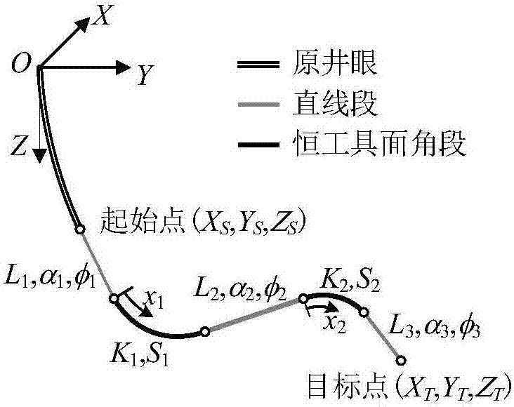
[0035] The wellbore track design adopts the North East coordinate system OXYZ, O is the wellhead, the X axis points to the true north, the Y axis points to the true east, and the Z axis points to the vertical direction. In order to meet the needs of trajectory design for directional wells and horizontal wells, two types of "straight line segment-constant tool face angle segment-straight segment" and "straight line segment-constant tool face angle segment-straight segment-constant tool face angle segment-straight segment" are established. The design model, in which the length of the straight line segment can be zero, can satisfy two typical orbital design requirements of defining the target position and simultaneously defining the target position and direction.

[0036] Two constant tool face angle track design models such as figure 1 with 2 As shown, its constraint equation is:

[0037]

[0038] Among them, ...

example 1

[0125] Example 1: The coordinates of the current point of a directional well are: X S = 100m, Y S =-100m, Z S =2000m; well inclination angle and azimuth angle are α 1 = 10°, φ 1 = 315°. The coordinates of the target point are: X T =200m, Y T =-1100m, Z T = 4000m. If you continue to drill into L in the current direction 1 =200m, and then the ramping capacity is K 1 =3° / 30m tool to adjust the wellbore trajectory. The design result is to drill S with a constant tool face angle ω=-33.28° 1 =235.54m and then use the stabilized drilling tool to drill L 2 =1821.75m can accurately reach the design target point. The wellbore trajectory data are shown in Table 1.

[0126] Table 1 Design data of directional well track (three-section track)

[0127]

example 2

[0128] Example 2: Coordinate X of the end point of a 3D horizontal well T =31.70m, Y T =-1288.80m, Z T =869.42m, horizontal section inclination angle α 3 =90.36°, azimuth φ 3 =270°, segment length L 3 =941.72m. Build-up from the vertical well section, the build-up point is deep L 1 =532m, curvature K 1 =K 2 = 6° / 30m, using the constant tool face angle method to design the wellbore trajectory.

[0129] Using the dual-constant tool-face angle orbit design model, the length, inclination angle, and azimuth angle of the corresponding circular arc orbit stable section are obtained, which are used as the initial value of the quasi-Newton method to solve the constant tool-face angle orbit constraint equation, and are calculated after 2 numerical iterations , and the result is L 2 =80.706m, α 2 =46.164°, φ 2 =277.686°, see Table 2 for borehole trajectory data.

[0130] Table 2 Horizontal well track design data (five-segment track)

[0131]

[0132] It can be seen from T...


PUM


Abstract

The invention relates to a trace control method, in particular to a constant tool face angle drilling trace control method, and belongs to the technical field of downhole drilling. The two typical three-dimensional constant tool face angle borehole trajectory designing models of defining the target point position and defining the target point position and the target entry direction at the same time are established, a design constraint equation is rapidly and flexibly solved according to different design requirements, and therefore the design has universality and flexibility and theoretical foundations are provided for designing and control of the borehole trajectory.

Description

technical field [0001] The invention relates to a trajectory control method, which belongs to the technical field of downhole drilling, in particular to a method for controlling a drilling trajectory with a constant tool face angle. Background technique [0002] With the development of directional drilling technology, higher requirements are put forward for the design and control of borehole trajectory. In directional drilling operations, most of the wellbore trajectories involved are three-dimensional wellbore trajectories, such as sidetracking horizontal wells, geosteering drilling and wellbore trajectories to be drilled. , Quickly drill to the target layer. [0003] The outstanding feature of the constant tool-face angle curve wellbore trajectory is that the borehole curvature, inclination angle change rate and tool-face angle are all constant, which is convenient for directional operation and can reduce drilling operation costs. As a typical wellbore trajectory model, i...

Claims


Application Information

Patent Timeline
IPC IPC(8): E21B44/00
CPCE21B44/00
Inventor 唐雪平洪迪峰盛利民窦修荣王家进高文凯王鹏彭烈新滕鑫淼蓝蓉管康彭浩
Owner BC P INC CHINA NAT PETROLEUM CORP
Why Eureka
Try Eureka