Air conditioner and dehumidifier combined device

A combination device and air conditioner technology, which is applied in the direction of refrigerators, compressors, mechanical equipment, etc., can solve the problems of equipment reliability decline, two-way solenoid valve sealing performance deterioration, refrigerant leakage, etc., and achieve good performance in preventing refrigerant leakage, Large amount of condensed water, the effect of product maturity

Pending Publication Date: 2017-09-22
胡少林
View PDF0 Cites 8 Cited by
  • Summary
  • Abstract
  • Description
  • Claims
  • Application Information

AI Technical Summary

Problems solved by technology

The more complex structure leads to an increase in cost and volume, and also leads to a decrease in the reliability of the equipment; in a heat pump system similar to an air conditioner, due to the high pressure of the refrigerant, the sealing of the two-way solenoid valve becomes poor, resulting in leakage of the refrigerant; there are Mature one-way shut-off valve, but lacks two-way shut-off valve for high-pressure refrigerant
If the refrigerant two-way shut-off valve is used reluctantly, it will lead to refrigerant leakage and failure caused by the shut-off valve, resulting in a solution that is theoretically feasible, but the actual product cannot be used stably. Experiments have proved this.

Method used


Image

  • Air conditioner and dehumidifier combined device
  • Air conditioner and dehumidifier combined device
  • Air conditioner and dehumidifier combined device

Examples


Embodiment 1

[0049] Example 1: Household Air Conditioner Dehumidifier Combined Device

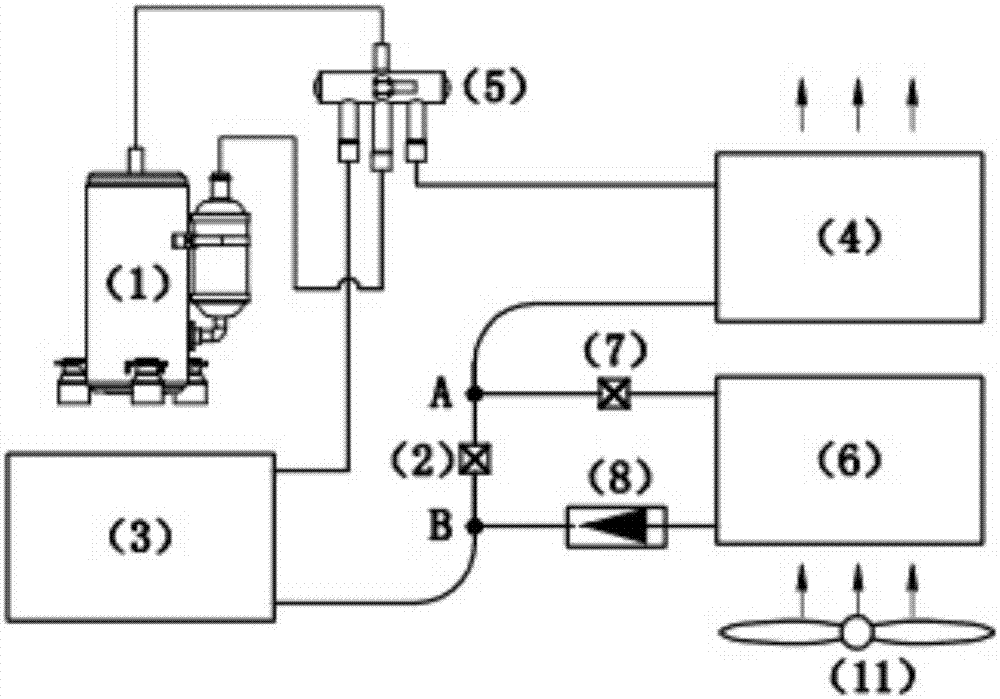
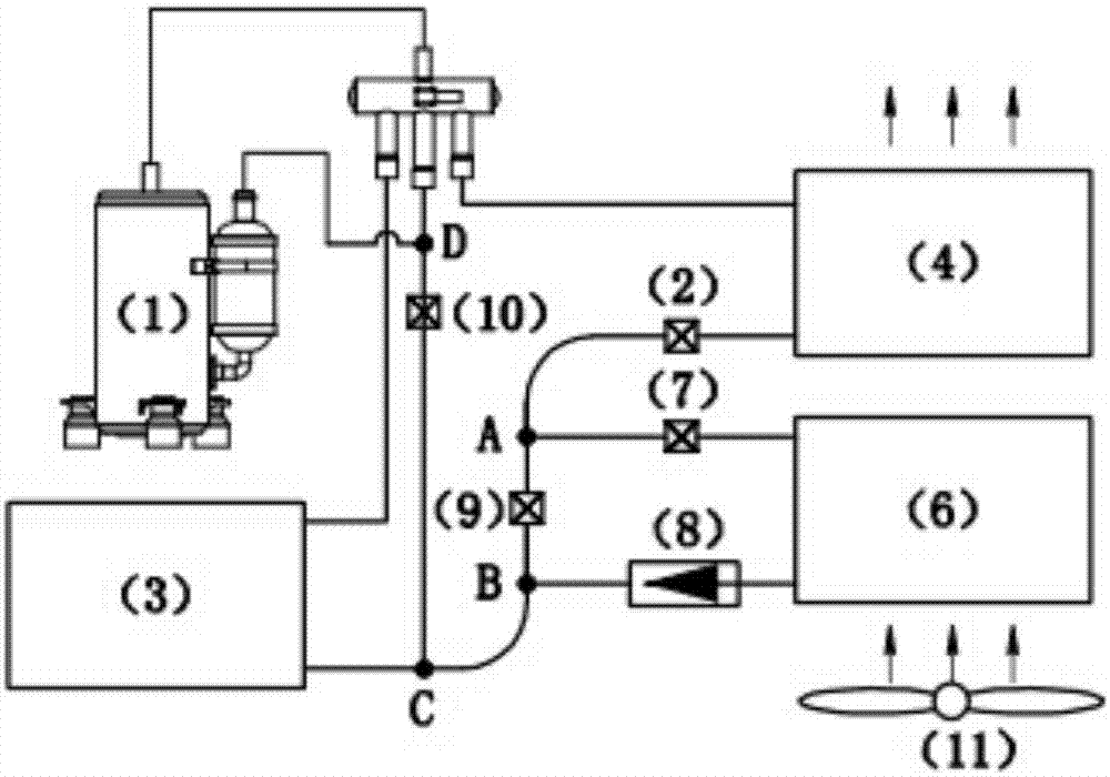
[0050] In this embodiment, the structural principles are as described in claims 1, 2, and 7. Structure diagram such as figure 1 , image 3 As shown, the indoor heat exchanger 4 in the indoor unit and the dehumidification evaporator 6 share an indoor fan 11, and the dehumidification evaporator is upstream of the air flow of the indoor heat exchanger, and all the air flowing through the dehumidification evaporator flows through the indoor heat exchange There is another air inlet in the indoor unit, and the air does not flow through the dehumidification evaporator but directly flows through the indoor heat exchanger; ensure that the air volume flowing through the indoor heat exchanger is more than 1.2 times the air volume flowing through the dehumidification evaporator.

[0051] The dehumidification cut-off valve 8 is a mechanical one-way valve, which only allows the refrigerant to flow from A to B in th...

Embodiment 2

[0054] Example 2: Combined device of frequency conversion household air conditioner and dehumidifier

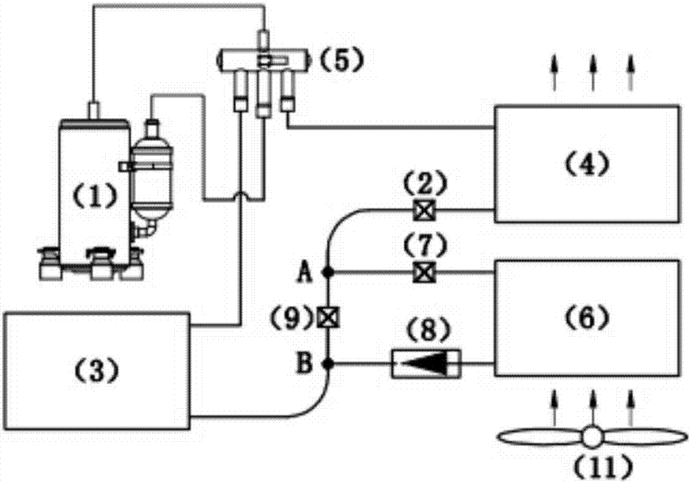
[0055] In this embodiment, the structure of the device is as described in claims 1, 3 and 4, and the device is a frequency conversion system. All the other are identical with embodiment 1.

[0056] The dehumidification cut-off valve 8 is a mechanical one-way valve. The air conditioning control valve 9 and the dehumidification control valve 7 are electronic expansion valves.

[0057] When the device is running, the electronic expansion valve 2 is not closed all the time.

[0058] When the device operates as an air conditioner, the electronic expansion valve 7 and the dehumidification stop valve 8 as the dehumidification control valve are closed, and the electronic expansion valve 9 as the air conditioning control valve is fully opened; when the device operates as a dehumidifier, the electronic expansion valve as the dehumidification control valve The expansion valve 7 is fu...

Embodiment 3

[0061] Embodiment 3: Combination device of commercial air conditioner and dehumidifier

[0062] In this embodiment, the setting of the valve is similar to that of Embodiment 1. The indoor heat exchanger 4 and the dehumidification evaporator 6 are respectively equipped with fans, wherein the fan of the dehumidification evaporator 6 is a speed-regulating fan, and the air inlet of the dehumidification evaporator 6 is an air outlet. A gas sensible heat exchanger is installed to exchange heat between the low-temperature outlet air of the dehumidification evaporator and the inlet air to reduce the temperature of the air entering the dehumidification evaporator. The bypass pipeline described above is installed in the outdoor unit. The power of the device is generally not less than 5 horsepower.

[0063] When the device is used as an air conditioner, the operation of each valve is the same as in Embodiment 1. The fan of dehumidification evaporator 6 does not work. The solenoid valv...


PUM


Abstract

The invention relates to an air conditioner and dehumidifier combined device. The air conditioner and dehumidifier combined device is characterized in that in a split air conditioner, a throttle valve (2) is arranged in an indoor unit, and a compressor is arranged in an outdoor unit. An air conditioner refrigerant pipeline with an outdoor heat exchanger (3) as the starting point, passing the throttle valve (2) and with an indoor heat exchanger (4) as the terminal point is defined as a pipeline S, and a dehumidification loop connected with the pipeline S in parallel is additionally arranged in the indoor unit. The dehumidification loop communicates with the pipeline S at the position A and the position B of the pipeline S, the position B is located on the starting point side of the pipeline S, and the position A is located on the terminal point side. The corresponding positions of components on the dehumidification loop are A, a dehumidification control valve (7), a dehumidification evaporator (6), a dehumidification check valve (8) and B. The two valves of the dehumidification loop are closed, and the device is the air conditioner. A valve piece between the position A and the position B of the pipeline S is closed, flowing of a refrigerant between the position A and the position B of the pipeline S is isolated, the two valves on the dehumidification loop are opened, the indoor heat exchanger is a condenser, and the device is a dehumidifier. During dehumidification, the volume of air flowing through the indoor heat exchanger is larger than the air volume of the dehumidification evaporator by 1.2 times. The device is ingenious, simple and reliable in structure, high in dehumidification efficiency, large in dehumidification amount, convenient to install, and capable of achieving two purposes.

Description

technical field [0001] The invention relates to an air conditioner and dehumidifier combined device, which not only has the functions of heating and cooling air conditioners, but also has the functions of a dehumidifier, and belongs to the field of control and adjustment of indoor air temperature and humidity. Background technique [0002] Air conditioners and dehumidifiers are commonly used equipment for regulating temperature and humidity in buildings. Both air conditioners and dehumidifiers are heat pump systems that use the same components and operate on the same principle. However, the existing air conditioners and dehumidifiers often only focus on their independent applications, and fail to fully combine their functions into one; After the dehumidifier, you need to purchase another dehumidifier. However, the existing household dehumidifiers have low power and dehumidification capacity, high noise, and increase the indoor temperature during operation in summer, which ...

Claims


Application Information

Patent Timeline
Patent Type & Authority Applications(China)
IPC IPC(8): F25B13/00F25B41/04F25B41/06F25B41/20F25B41/30
CPCF25B13/00F25B2400/19F25B2600/25F25B2600/2513F25B2313/02741F25B2313/0292F25B41/30F25B41/20F25B41/31
Inventor 胡少林
Owner 胡少林
Why Eureka
Try Eureka