Rotatable heat sink with internal convection

A technology of radiator and rotating ground, which is applied in the direction of indirect heat exchanger, heat exchanger type, moving pipe heat exchanger, etc., and can solve the problem of frequent service life

Inactive Publication Date: 2017-09-22
CHRISTIE DIGITAL SYST USA INC
View PDF6 Cites 8 Cited by
  • Summary
  • Abstract
  • Description
  • Claims
  • Application Information

AI Technical Summary

Problems solved by technology

Many of these liquid cooling methods also require rotating mechanical fluid seals, wh...

Method used


Image

  • Rotatable heat sink with internal convection
  • Rotatable heat sink with internal convection
  • Rotatable heat sink with internal convection

Examples


Embodiment Construction

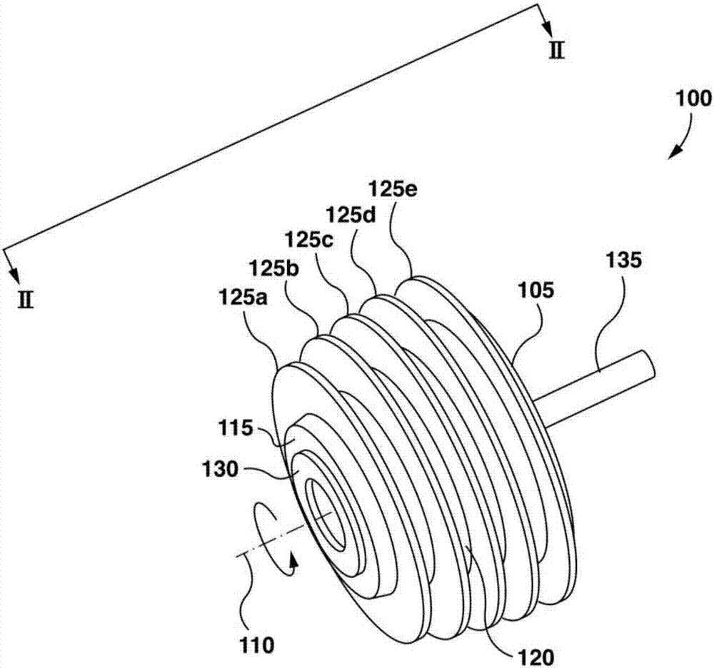
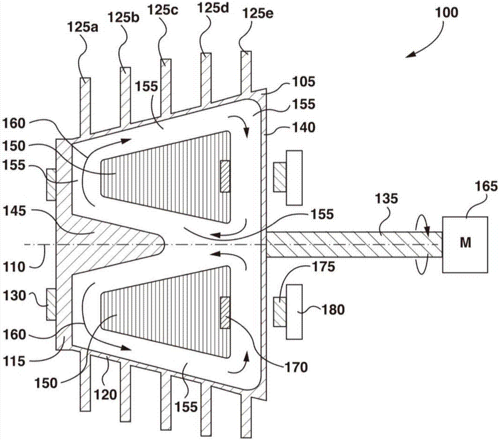
[0041] figure 1 A perspective view of a radiator arrangement 100 comprising a radiator 105 rotatable about an axis of rotation 110 is shown. The heat sink 105 includes a first end wall 115 and a second end wall (in figure 1not visible in ), both are arranged radially on the axis of rotation 110 . The heat sink 105 also includes side walls 120 that cooperate with the first end wall 115 and the second end wall to define the heat sink 105 . The radiator 105 is configured to enclose a cooling fluid. Device 100 also includes fins 125a , 125b , 125c , 125d , and 125e (collectively fins 125 ) extending radially from the outer surface of sidewall 120 . An annular layer of light wavelength converting material 130 is disposed on the outer surface of the first end wall 115 . A shaft 135 extends from the second end wall along the axis of rotation 110 . Shaft 135 may be used to couple device 100 to a source of mechanical actuation, such as an electric motor.

[0042] When the excitat...


PUM


Abstract

According to the present specification there is provided a rotatable heat sink device which comprises a heat sink configured to enclose a cooling fluid, and the heat sink is rotatable about a rotational axis. The heat sink, in turn, comprises a first portion configured to receive thermal energy from a source external to the heat sink, and a second portion configured to dissipate at least a portion of the thermal energy to surroundings external to the device. The device further comprises an optical wavelength conversion material disposed on an outside surface of the first portion of the heat sink, and an agitator disposed inside the heat sink. The agitator is rotationally independent of the heat sink and is configured to promote circulation of the cooling fluid between the first portion and the second portion.

Description

[technical field] [0001] The present invention relates to heat sinks, and in particular, to rotatable heat sinks for light wavelength converting materials. [Background technique] [0002] In many image projection systems, optical wavelength converting materials are used as light sources. The wavelength conversion material is excited by excitation light, such as a laser, and in response, the conversion material emits light at a wavelength different from that of the excitation light. Many wavelength converting materials such as phosphors and quantum dots (QDs) are thermally limited. The high energy density at the excitation spot is typically reduced by rotating the conversion material to move the excitation spot, thereby distributing the excitation heat throughout the larger volume of conversion material. The conversion material can also be placed on a rotating solid disk, which can act as a heat sink and can absorb and dissipate some of the excitation heat from the conversi...

Claims


Application Information

Patent Timeline
IPC IPC(8): G03B21/16
CPCG03B21/16F28D11/02F28D15/0208F28D2015/0291F28D2021/0029F28F5/00F28F13/125F28F13/18F28F2245/06F21V29/502F21V9/38G03B21/204F21V29/56F21V29/713F21V29/74
Inventor 丹尼尔·罗伯特·阿德马格拉汉姆·希尔
Owner CHRISTIE DIGITAL SYST USA INC
Why Eureka
Try Eureka