
Variable power point tracking control method of two-stage type no-energy-storage photovoltaic virtual synchronization machine

A virtual synchronous machine and variable power point technology, applied in photovoltaic power generation, AC network circuits, electrical components, etc., can solve practical application difficulties, cannot apply two-stage photovoltaic system, increase the cost and maintenance workload of photovoltaic power generation system, etc. problem, to achieve the effect of improving the system voltage and frequency stability

Active Publication Date: 2017-09-22
NORTH CHINA ELECTRIC POWER UNIV (BAODING) +1
View PDF4 Cites 48 Cited by
  • Summary
  • Abstract
  • Description
  • Claims
  • Application Information

AI Technical Summary

Problems solved by technology

Although this method can realize the characteristics of the virtual synchronous machine, the configuration of the energy storage device increases the cost and maintenance workload of the photovoltaic power generation system, as well as additional installation space, which brings great difficulties to practical applications.
Using the self-adaption of photovoltaic cells, a virtual synchronous machine control strategy without energy storage suitable for single-stage photovoltaic systems can be obtained, but this method cannot be applied to two-stage photovoltaic systems used in distributed grids

Method used


Image

  • Variable power point tracking control method of two-stage type no-energy-storage photovoltaic virtual synchronization machine
  • Variable power point tracking control method of two-stage type no-energy-storage photovoltaic virtual synchronization machine
  • Variable power point tracking control method of two-stage type no-energy-storage photovoltaic virtual synchronization machine

Examples


Embodiment Construction

[0028] The present invention provides a two-stage non-energy storage photovoltaic virtual synchronous machine control method for variable power point tracking. The present invention will be further described below in conjunction with the accompanying drawings.

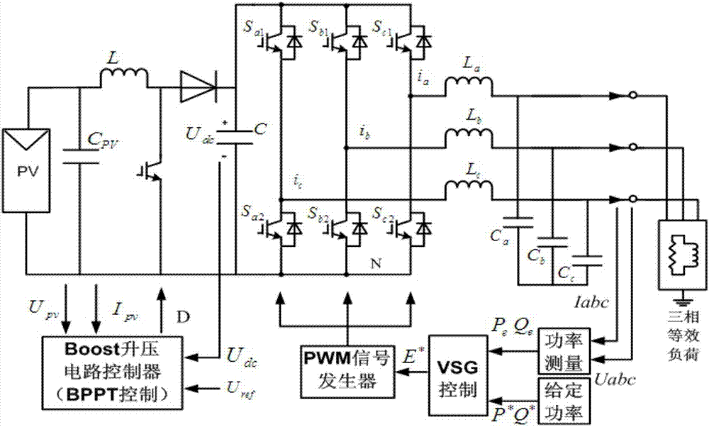
[0029] figure 1 Shown is the topology of a two-stage three-phase photovoltaic virtual synchronous machine. The photovoltaic battery PV is connected to the local load or the grid through the Boost circuit, inverter and LC filter, and the three-phase equivalent load is used to replace the local load and the load required by the grid. Sum. Photovoltaic cells PV and Boost circuits are modeled as prime movers that provide energy consistent with load variations, and inverter and LC circuits can model the rest of the synchronous generator. How the Boost circuit adjusts the output power of the photovoltaic cell to provide the same energy as the load demand, and how the inverter simulates the inertia and damping of the synchro...


PUM


Abstract

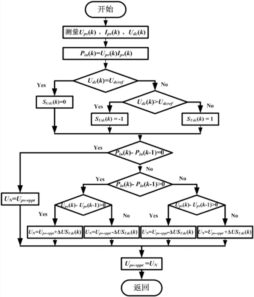
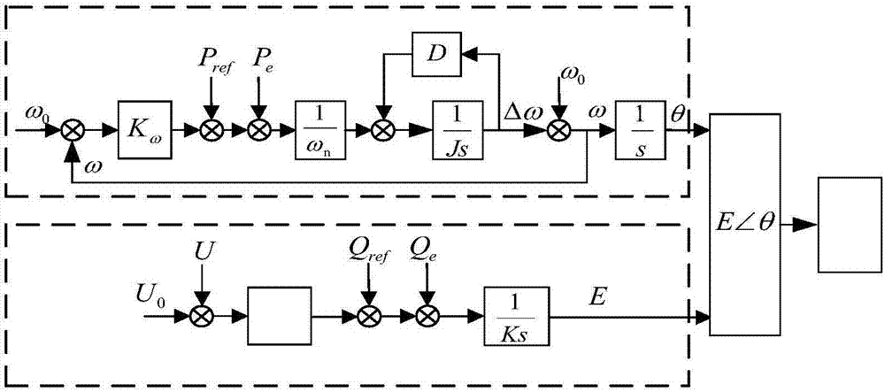
The invention discloses a variable power point tracking control method of a two-stage type no-energy-storage photovoltaic virtual synchronization machine, and belongs to the technical field of new energy power systems and micro-grids. The variable power point tracking control method comprises the steps of changing an original single augmented variable mode into a mode of judging whether an SUdc(k) represented DC bus voltage value is steady based on a DC bus voltage through improving the conventional perturbation observation MPPT (Maximum Power Point Tracking) method for DC / DC circuit control in a two-stage type photovoltaic system; and giving full play of a regulation effect of a DC / DC converter on the output power of a photovoltaic battery. Inertia support for the virtual synchronization machine and energy supply needed by one regulation are realized under the precondition of not adding any energy storage device; and control of the photovoltaic virtual synchronization machine is realized by combining a VSG control strategy of an inverter. When a load changes suddenly or the external environment condition changes, the photovoltaic system can reflect the characteristics of the synchronization machine, can keep steady system voltage / frequency and power balance, and can realize variable power point tracking relevant to the DC bus voltage.

Description

technical field [0001] The invention belongs to the technical field of new energy power systems and microgrids, and in particular relates to a two-stage non-energy storage photovoltaic virtual synchronous machine control method for variable power point tracking. Background technique [0002] With the continuous improvement of the penetration rate of photovoltaic power generation systems, its grid-connected equipment needs to gradually change the thinking of "just power generation, not the grid". How to rely on flexible and controllable power electronics technology to improve the reliability of photovoltaic systems and make them a "participant" in jointly maintaining the safety and stability of the power grid is of great significance. In the prior art, photovoltaic cells are integrated into the grid or directly supply power to loads through at least one level of power electronic converters. The extensive use of power electronic converters and their control technologies makes ...

Claims


Application Information

Patent Timeline
IPC IPC(8): H02J3/38
CPCH02J3/385Y02E10/56
Inventor 颜湘武赵佳乐张波
Owner NORTH CHINA ELECTRIC POWER UNIV (BAODING)
Learn More