Control device for ultrasonic planar array probe

A control device and an area array technology, applied in the field of medical ultrasound probe control circuits, can solve the problems of increasing system complexity and cost, failing to meet the amplitude requirements of the external acquisition system, and being susceptible to external interference, so as to avoid crosstalk between channels and Effect of external electromagnetic interference and improvement of system complexity

Active Publication Date: 2017-09-26
HUAZHONG UNIV OF SCI & TECH
View PDF6 Cites 7 Cited by
  • Summary
  • Abstract
  • Description
  • Claims
  • Application Information

AI Technical Summary

Problems solved by technology

Multiplexing can effectively reduce the array element density, but requires additional circuit system and control software, which increases the complexity and cost of the system
Non-patent literature (BioMedical Engineering OnLine 2014, 13:76) discloses a protection circuit for high-frequency ultrasonic probes, the protection circuit is based on a MOSFET-based switching mode power supply (SMPS, Switching Mode Power Supply) high-frequency probe Protect the circuit, which can reduce the insertion loss of the circuit and obtain higher signal sensitivity, but because the circuit uses a discrete element field effect tube: first, the circuit structure is relatively complex and is easily affected by external interference; second, the discrete Type components make the time of sending and receiving signals of different array elements of the probe asynchronous, which affects the precision of detection; third, the limiting circuit of the receiving part cannot limit the transmitted signal to a smaller amplitude range, and cannot achieve external acquisition. System Amplitude Requirements
[0004] In addition, for the current real-time three-dimensional ultrasonic imaging system that has attracted much attention, there are problems such as a large number of array probe elements, a large number of channels, and a large amount of data. If the existing high-frequency ultrasonic probe control device and control method are used, the circuit structure It will be more complicated, and the anti-interference will be worse, which will affect the image quality

Method used


Image

  • Control device for ultrasonic planar array probe
  • Control device for ultrasonic planar array probe
  • Control device for ultrasonic planar array probe

Examples


Embodiment 1

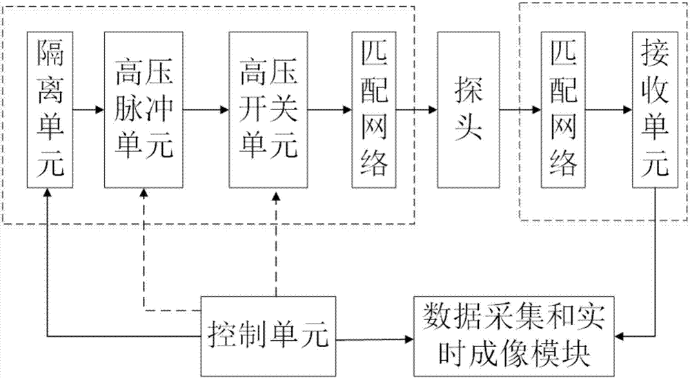
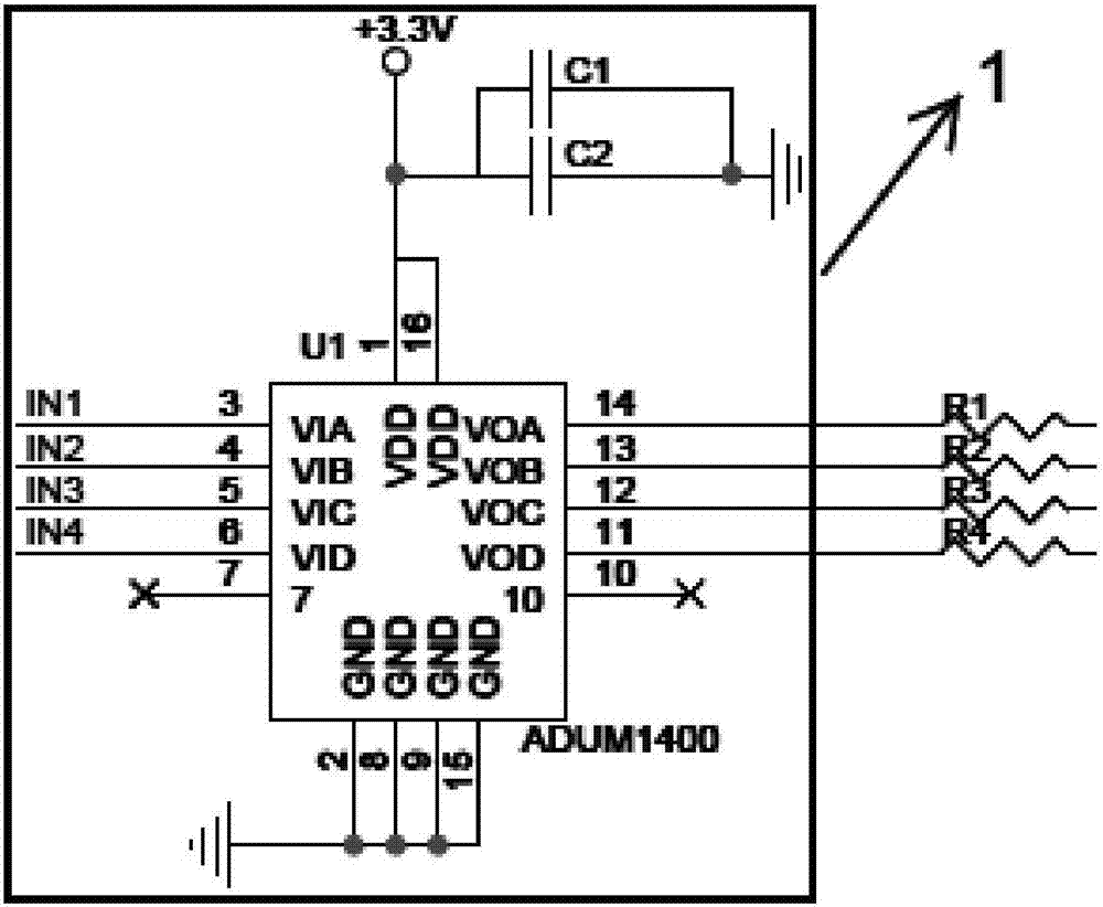
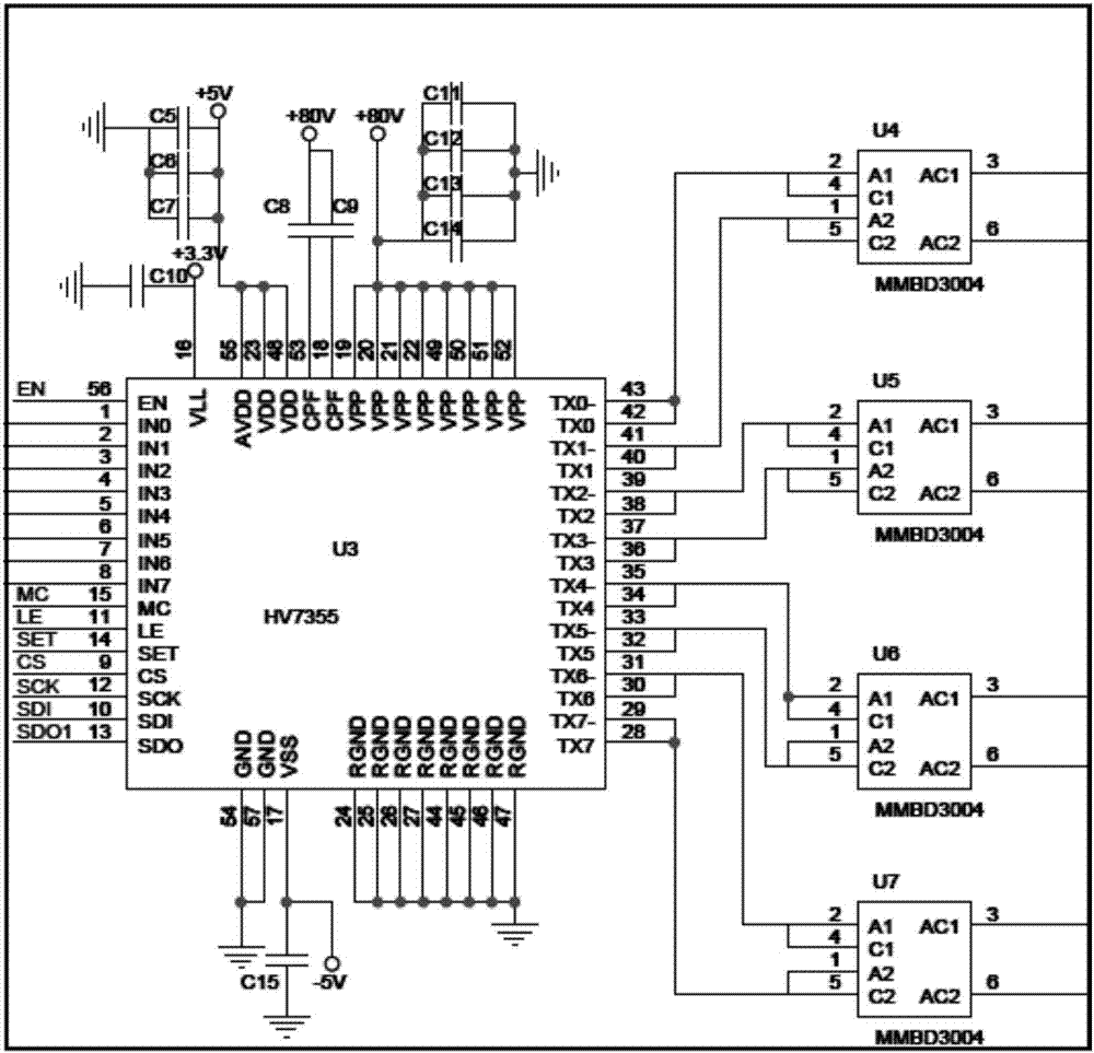
[0049] This embodiment discloses a control device that can be used for a two-dimensional ultrasonic array probe, such as figure 1 , Figure 2A to Figure 2F As shown, it includes a control unit, an isolation unit 1, a high-voltage pulse unit 2, a high-voltage switch unit 3, a matching network 4 (including a first matching network and a second matching network), and a receiving unit 5; The outputs are respectively connected to the input ends of the high-voltage switch unit 3, and the high-voltage pulse signal output by the high-voltage switch unit 3 is output to the external area array probe through the first matching network, and the ultrasonic signal generated after the area array probe is excited passes through the second matching The output of the network is sent to the input end of the receiving unit 5, converted into an electrical signal by the receiving unit 5, and finally enters an external acquisition system for processing and real-time imaging.

[0050] Wherein, what ...


PUM


Abstract

The invention discloses a control device for an ultrasonic planar array probe. The control device comprises an isolation unit (1), a high-voltage pulse unit (2), a high-voltage switch unit (3), a matching network, a receiving unit (5) and a control unit, wherein a first output end of the control unit is connected with the input end of the isolation unit (1); a second output end of the control unit is connected with a first input end of the high-voltage pulse unit (2); a third output end of the control unit is connected with a first input end of the high-voltage switch unit (3); the control unit is used for supplying low-voltage pulse signals with the amplitude range not larger than 5V to the isolation unit (1), sending a preset first control signal to the high-voltage pulse unit (2) and sending a preset second control signal to the high-voltage switch unit (3). According to the method, control over a whole row of or a whole column of or multiple rows and columns of array elements of the probe can be achieved at the same time, so that the complexity and instability of a traditional ultrasonic system circuit using discrete components are eliminated.

Description

technical field [0001] The invention belongs to the field of control circuits of medical ultrasonic probes, and more specifically relates to a control device for ultrasonic array probes, especially applicable to two-dimensional ultrasonic array probes. Background technique [0002] Compared with the traditional B-ultrasound, the real-time 3D ultrasonic diagnostic instrument based on the 2D area array can provide more comprehensive and detailed human body information, and has been gradually applied in clinical examination and diagnosis. At present, the high-end ultrasound products of major foreign medical imaging companies have realized real-time three-dimensional ultrasound imaging technology based on two-dimensional area arrays. Due to the multi-transmission / reception channels of fully connected area array probes, electromagnetic crosstalk is easy to occur between array elements, and the sensitivity of signals And the signal-to-noise ratio is reduced, and the signal strengt...

Claims


Application Information

Patent Timeline
Patent Type & Authority Applications(China)
IPC IPC(8): A61B8/00
Inventor 尉迟明丁明跃李旭宋俊杰钟小丽李春雨杨佳丽
Owner HUAZHONG UNIV OF SCI & TECH
Why Eureka
Try Eureka