
Drying oven structure reducing film surface influence

A technology of oven and film surface

Pending Publication Date: 2017-09-26
江阴华美光电科技有限公司
View PDF3 Cites 2 Cited by
  • Summary
  • Abstract
  • Description
  • Claims
  • Application Information

AI Technical Summary

Problems solved by technology

The cross-sectional area of ​​the air duct is designed as much as possible to maintain the lowest air velocity. The oven in the air duct has an air inlet room and an air outlet. The drying room is between the two air inlet rooms, and the air inlet is facing the drying room. The air nozzle, the air inlet chamber is equipped with an air inlet pipe, and the circulation air outlet of the main body of the oven draws out the air through the heater and then returns to the air inlet pipe to form a recycling, so as to save energy; in addition, its air inlet directly faces The substrate (coated product) has no effective guiding and diverting devices, resulting in uneven drying of the product, cracking and curling due to local overdrying, and low drying efficiency; due to poor ventilation, it is easy to cause solvent gas inside the box If the concentration is too high, it will cause the equipment to alarm and shut down or even catch fire. The function of the nozzle is to form a good air flow field in the dry area through the hot air with uniform wind speed and stable pressure. If the speed of the hot air fluctuates too much when spraying, uneven drying will occur. The high wind speed area will cause the pole piece to vibrate or cause problems, and the low wind speed area will make the pole piece dry incompletely. Therefore, the structure of the drying box nozzle is particularly important

Method used


Image

  • Drying oven structure reducing film surface influence

Examples


Embodiment Construction

[0020] The present invention will be further described in detail below in conjunction with the accompanying drawings and embodiments.

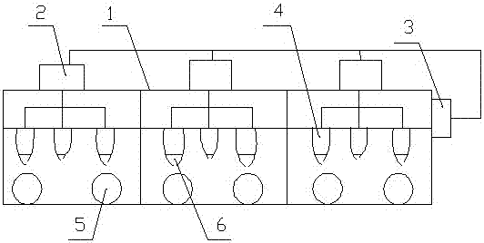
[0021] Such as figure 1 As shown, an oven structure that reduces the influence of the film surface in this embodiment includes an oven box 1, a circulation fan 2 and an exhaust fan 3. The oven box 1 is 28 meters from the beginning to the end, and is divided into low-temperature sections. The first leveling zone (temperature 80°~90°), the high temperature curing zone (temperature 140°~150°) in the high temperature section and the second leveling zone (temperature 130°~100°) in the low temperature section, the temperature From low to high, and then from high to low, air outlet channels 4 are arranged at three sections inside the oven box 1, the air outlet channels 4 are evenly arranged and communicated with the oven box 1, and the air outlet channels 4 are evenly arranged. Arranged and arranged in parallel with the guide rollers 5 below, an air...


PUM


Abstract

The invention discloses a drying oven structure reducing the film surface influence. The drying oven structure comprises a drying oven body, circulation fans and an exhaust fan. The drying oven body is divided into a low-temperature-section first flash-off area, a high-temperature-section high-temperature curing area and a low-temperature-section second flash-off area. Three sections in the drying oven body are provided with air outlet channels. The air outlet channels are evenly formed and communicate with the drying oven body. The air outlet channels are evenly formed and are parallel to guiding rollers below the air outlet channels. The air outlet channels are formed above the corresponding guiding rollers and between the corresponding guiding rollers. The circulation fans communicate with the air outlet channels in the drying oven body through air pipes. The exhaust fan communicates with the drying oven body. The drying oven structure is provided with a structure feeding and distributing flow evenly in the drying oven, so that the discharge air amounts of all air ports in the oven body are consistent, the pressure is balanced, the drying uniformity is improved, all points of products are synchronously dried, and thus the drying efficiency is improved.

Description

technical field [0001] The invention relates to the technical field of thin film coating, in particular to an oven structure for reducing the influence of the film surface. Background technique [0002] The existing coating oven structure is generally divided into chamber body design, hot air circulation system design and conveying system design. The chamber body is used to maintain the temperature in the oven, reduce heat loss, improve drying efficiency, and is also the basis for installing other parts of the oven. In general, the mechanical calculation of the insulation board (such as strength calculation, deflection calculation, etc.) and the thickness calculation of the insulation board should be carried out during the design. The thickness of the insulation board is determined according to the temperature of the oven. The common thickness of the insulation board is 100mm, 125mm and 160mm. Commonly used insulation materials are rock wool, aluminum silicate fiber, glass...

Claims


Application Information

Patent Timeline
Patent Type & Authority Applications(China)
IPC IPC(8): B05D3/04
CPCB05D3/0413
Inventor 王上丹吴祥赵伟达
Owner 江阴华美光电科技有限公司
Learn More