Method for producing molten iron using electric furnace

A technology of molten iron and electric furnace, applied in the direction of electric furnace, furnace, charge control, etc., can solve the problem of the distance change between the auxiliary burner and iron scrap, achieve efficient heating or melting, reduce power consumption, and shorten the operation time.

Inactive Publication Date: 2017-09-26
JFE STEEL CORP
View PDF8 Cites 3 Cited by
  • Summary
  • Abstract
  • Description
  • Claims
  • Application Information

AI Technical Summary

Problems solved by technology

[0005] Even if the burner described in Patent Document 1 is used as an auxiliary burner, during the operation of the electric furnace, the distance between the auxiliary burner and the iron scrap will change due to charging, additional charging, and melting of the iron scrap

Method used


Image

  • Method for producing molten iron using electric furnace
  • Method for producing molten iron using electric furnace
  • Method for producing molten iron using electric furnace

Examples


Embodiment

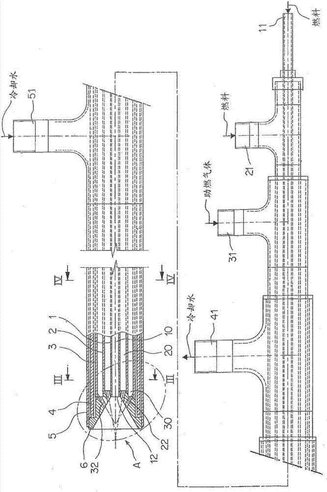
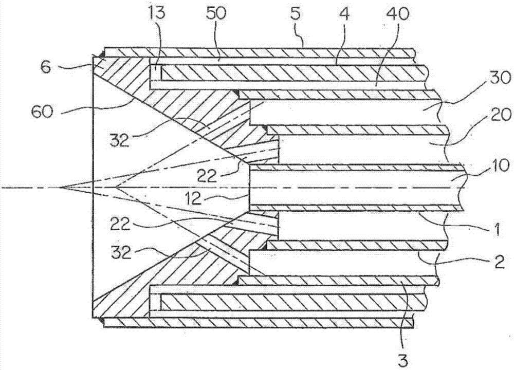
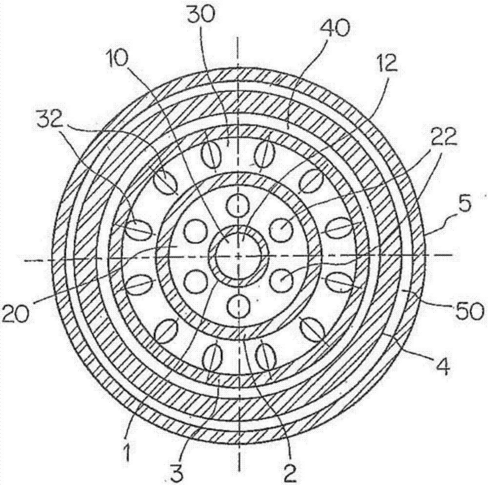
[0065] exist Figure 1 ~ Figure 4 In the auxiliary burner of the structure shown, the flame temperature of the burner was measured using two kinds of fuels having different ignition temperatures. The output of the burner is 30 Mcal / h.

[0066]As fuel, LPG (gas fuel) and fine powder carbon (solid fuel) are used. As fine powder carbon, lignite with a calorific value of 6200kcal / kg and a particle size of d(90)=100μm is used, and the flow rate of nitrogen gas for fine powder carbon transportation is 1.2Nm 3 / h.

[0067] In the test, the solid fuel ratio was set to 10% and 50%, and the flame temperatures at 0.2 m and 0.4 m from the front end of the burner were measured using an optical fiber thermometer and an R-type thermocouple.

[0068] Express the relationship between the proportion of solid fuel in the fuel and the flame temperature in Figure 6 middle. Under the condition that the gas fuel (LPG) ratio was high, the flame temperature at the position of 0.2 m near the burn...


PUM


Abstract

In the present invention, in a method in which iron scrap is melted in an electric furnace provided with an auxiliary burner to obtain molten iron, iron scrap is efficiently heated or melted using the auxiliary burner. When heating and melting the iron scrap inside the electric furnace by using the auxiliary burner, at least two types of fuel which have different ignition temperatures and / or combustion speeds are used as the fuel for the auxiliary burner. The ratio between the at least two types of fuel is changed in accordance with the distance between the auxiliary burner and the iron scrap which is to be heated and melted using the auxiliary burner. By utilizing the ratio between the at least two types of fuel, the length of the flame of the auxiliary burner can be freely adjusted, and the iron scrap can be efficiently heated or melted.

Description

technical field [0001] The present invention relates to a method of melting ferrous scrap to produce molten iron in an electric furnace equipped with an auxiliary burner. Background technique [0002] In the case of using an electric furnace to melt ferrous scrap, although the ferrous scrap around the electrode melts rapidly, the melting of the ferrous scrap at a place far from the electrode, that is, at a cold spot, is slow, so the melting speed of the ferrous scrap in the furnace is increased. uneven. Therefore, the overall operating time in the furnace is limited by the melting rate of the ferrous scrap at the cold spot. [0003] Therefore, in order to eliminate the inhomogeneity of the melting speed of such iron scraps and to melt the whole iron scraps in the furnace with a better balance, an auxiliary burner is installed at the cold spot, and the auxiliary burner is used to A method of preheating, cutting, and melting ferrous scrap at cold spots. [0004] As such an ...

Claims


Application Information

Patent Timeline
Patent Type & Authority Applications(China)
IPC IPC(8): F27B3/22C21C5/52F23D17/00F27D3/16
CPCC21C5/52F23D17/00F27B3/22F27D3/16Y02P10/20
Inventor 小泽纯仁浅沼稔松野英寿
Owner JFE STEEL CORP
Why Eureka
Try Eureka