Vehicle-mounted new energy battery pack

A battery pack, new energy technology, applied in battery pack components, batteries, battery electrodes, etc., can solve the problem that the battery cannot meet the power demand of electric vehicles, achieve good cycle stability, prevent gas generation, and high phase purity. Effect

Inactive Publication Date: 2017-10-03
江苏昊科汽车空调有限公司
View PDF10 Cites 8 Cited by
  • Summary
  • Abstract
  • Description
  • Claims
  • Application Information

AI Technical Summary

Problems solved by technology

[0004] In order to solve the above technical problems, the present invention provides a vehicle-mounted new energy battery pack to solve the problem that a single battery cannot meet the power demand of an electric vehicle, and that the pouch battery can work safely and normally during the operation of a lithium-ion powered vehicle

Method used


Image

  • Vehicle-mounted new energy battery pack
  • Vehicle-mounted new energy battery pack

Examples


Embodiment 1

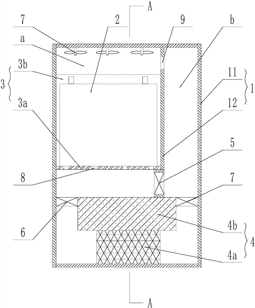
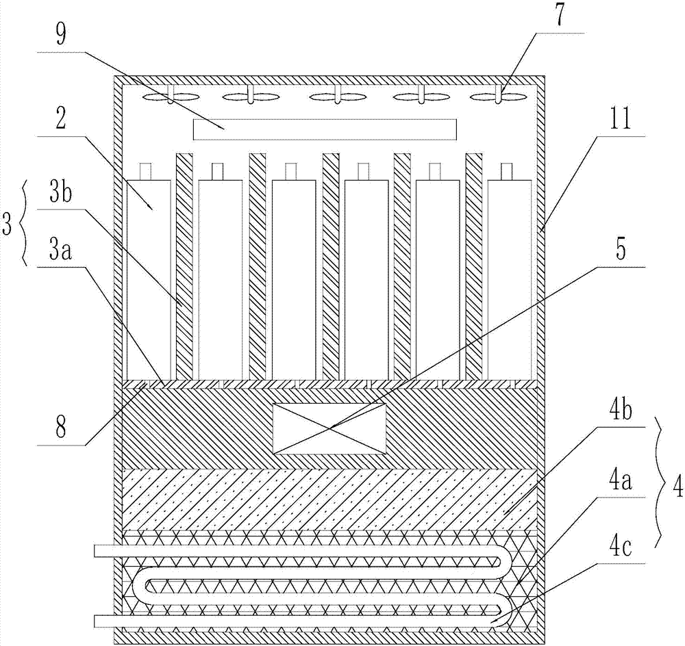
[0025] Such as figure 1 and figure 2 As shown in , a vehicle-mounted new energy battery pack includes a battery box 1 and a plurality of battery bodies 2 placed in the battery box 1. The battery box 1 includes a closed box 11, and the closed box 11 A space divider 12 is vertically arranged, and the space divider 12 divides the battery box 1 into a battery placement area a and a heat dissipation area b, and a battery fixing frame 3 is horizontally arranged in the battery placement area a, and the The battery holder 3 includes a horizontal support plate 3a, on which the vent hole 8 is opened, and the sides of the horizontal support plate 3a are connected with the inner wall of the corresponding battery box 1 and the space separation plate 12 respectively. A plurality of the battery bodies 2 are placed in parallel on the horizontal support plate 3a, and a battery separator 3b is arranged between two adjacent battery bodies 2, and the lower end of the battery separator 3b is con...

Embodiment 2

[0036] Such as figure 1 and figure 2 As shown in , a vehicle-mounted new energy battery pack includes a battery box 1 and a plurality of battery bodies 2 placed in the battery box 1. The battery box 1 includes a closed box 11, and the closed box 11 A space divider 12 is vertically arranged, and the space divider 12 divides the battery box 1 into a battery placement area a and a heat dissipation area b, and a battery fixing frame 3 is horizontally arranged in the battery placement area a, and the The battery holder 3 includes a horizontal support plate 3a, on which the vent hole 8 is opened, and the sides of the horizontal support plate 3a are connected with the inner wall of the corresponding battery box 1 and the space separation plate 12 respectively. A plurality of the battery bodies 2 are placed in parallel on the horizontal support plate 3a, and a battery separator 3b is arranged between two adjacent battery bodies 2, and the lower end of the battery separator 3b is con...


PUM


Abstract

The invention discloses a vehicle-mounted new energy battery pack. The vehicle-mounted new energy battery pack comprises a battery box and multiple battery bodies arranged in the battery box; the battery box comprises a sealed type box body; a space partition plate is vertically arranged in the sealed type box body; the battery box is divided by the space partition plate into a battery placement region and a heat dissipation region; a fan is arranged on the battery box top plate above the battery placement region; a temperature detector is arranged in the battery placement region; multiple ventilating holes are formed in a battery fixation frame in the battery placement region; the ventilating holes are connected with the heat dissipation region to from an air circulation channel; and an air cooling apparatus is arranged in the air circulation channel. Compared with the prior art, the battery pack is arranged in the sealed box body according to the structure of the vehicle-mounted new energy battery pack, so that effects of thermal insulation and waterproofness are realized; by virtue of divisional setting, the temperature field distribution in the battery box can be improved; and by virtue of the battery bodies, the high-rate discharging performance of the lithium battery is improved, and excellent electronic conductivity and ionic conductivity and high high-rate charging-discharging performance are represented.

Description

technical field [0001] The invention relates to the technical field of electric vehicles, in particular to a vehicle-mounted new energy battery pack. Background technique [0002] With the improvement of people's requirements for environmental protection, more and more attention has been paid to the research and application of new energy vehicles. Lithium-ion powered vehicles are one of the representatives of new energy vehicles. The key technology of lithium-ion powered vehicles is lithium-ion batteries. Many factors need to be considered in its design. On the one hand, ensure that the performance of the battery meets the needs of the vehicle, and on the other hand, ensure that the battery has sufficient safety and reliability. The pouch battery is a high-performance battery composed of positive electrode, negative electrode, electrolyte and packaging film. It can be charged and discharged at a high rate and has a long service life, so it is widely used in the field of new ...

Claims


Application Information

Patent Timeline
Patent Type & Authority Applications(China)
IPC IPC(8): H01M2/10H01M10/48H01M10/613H01M10/617H01M10/625H01M10/655H01M10/6563H01M4/36H01M4/485H01M4/583H01M10/0569
CPCH01M4/362H01M4/485H01M4/583H01M10/0569H01M10/482H01M10/486H01M10/613H01M10/617H01M10/625H01M10/655H01M10/6563H01M2220/20H01M2300/0037H01M50/20Y02E60/10
Inventor 曹靖
Owner 江苏昊科汽车空调有限公司
Why Eureka
Try Eureka