Rotor and dispersion machine for dispersing materials

A disperser and rotor technology, applied in grain processing and other directions, can solve the problems of dispersion failure, poor equipment structure optimization, increased energy consumption and material consumption, etc., to reduce the possibility of secondary agglomeration, uniform and stable material particle size, and production. The effect of low processing cost

Pending Publication Date: 2017-10-10
东莞鸿凯工程设备有限公司
View PDF7 Cites 1 Cited by
  • Summary
  • Abstract
  • Description
  • Claims
  • Application Information

AI Technical Summary

Problems solved by technology

[0005] 1. The equipment structure is poorly optimized, the dispersion effect is not ideal, and it can only play the role of stirring;
[0006] 2. The structure of the equipment is complex, the cost of design, manufacture and processing is high. At the same time, the dispersion efficiency is low. During the dispersion process, due to the effects of various physical factors such as abrasives and flywheel edge cutting and extrusion, the material molecules are often cut into pieces. , and due to Brownian motion and van der Waals force, the material molecules will reunite, which will lead to dispersion failure or poor dispersion effect
Although the dispersion effect can be improved by prolonging the operation time, it will reduce the production capacity and increase the energy consumption and material consumption.

Method used


Image

  • Rotor and dispersion machine for dispersing materials
  • Rotor and dispersion machine for dispersing materials
  • Rotor and dispersion machine for dispersing materials

Examples


Embodiment 1

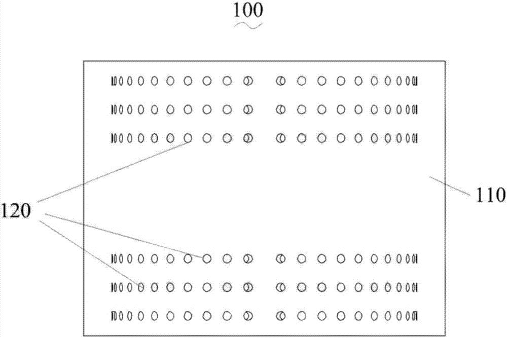
[0049] refer to figure 1 and figure 2 , in this embodiment, a rotor 100 for dispersing materials is proposed, and the purpose of dispersing materials is achieved by rotating the rotor 100 at a high speed.

[0050] The rotor 100 is a rotating body structure.

[0051] The surface formed by a plane curve or straight line rotating around a fixed line in its plane is called a surface of revolution, and the geometry formed by a closed surface of revolution is a solid of revolution. Wherein, the fixed line is called the center line of the rotating body.

[0052] In this embodiment, the rotor 100 is configured in a cylindrical shape.

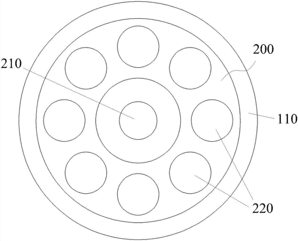
[0053] Such as image 3As shown, the rotor 100 includes an outer wall 110, wherein the interior of the rotor 100 is a hollow structure, so that the interior of the rotor 100 can be used to accommodate materials to be dispersed.

[0054] Since the rotor 100 is cylindrical, the outer surface of the outer wall 110 is a cylindrical surface. Meanwhile...

Embodiment 2

[0071] In this embodiment, a disperser is proposed, which includes a high-speed motor and a rotor 100 for dispersing materials.

[0072] High-speed motors generally refer to motors whose speed exceeds 10000r / min. Due to the high speed of the high-speed motor, the power density of the motor is high. At the same time, the height motor has a small moment of inertia and fast dynamic response.

[0073] In this embodiment, the high-speed motor can be selected with a rotation speed of 15000 r / min.

[0074] Such as figure 1 , figure 2 and image 3 As shown, wherein, the rotor 100 is a rotating body structure. In this embodiment, the rotor 100 is configured in a cylindrical shape.

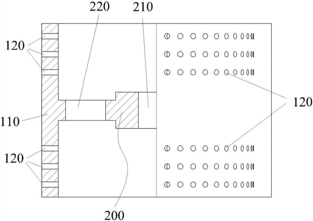
[0075] The rotor 100 includes an outer wall 110 , wherein the interior of the rotor 100 is a hollow structure. Among them, the materials to be dispersed are stored in the hollow structure.

[0076] In order to disperse the material more evenly, the outer surface and the inner surface of the outer w...


PUM


Abstract

The invention discloses a rotor and a dispersion machine for dispersing materials. According to the rotor and the dispersion machine for dispersing the materials, the rotor is of a rotating body structure and comprises an outer wall, and the interior of the rotor is of a hollow structure; a support frame is arranged in the hollow structure and fixedly connected with the rotor; a connecting hole used for mounting an input shaft which drives the rotor to rotate at high speed is formed in the support frame, and a material flow hole is further formed in the support frame; and material dispersion holes distributed in an annular array are formed in the outer wall, and penetrate through the outer wall. The dispersing efficiency of the rotor and the dispersion machine is high, accordingly the energy consumption is reduced, energy is saved and environment is protected; and meanwhile, the rotor and the dispersion machine are simple in structure, and low in manufacturing and processing cost.

Description

technical field [0001] The invention relates to the technical field of material dispersion, in particular to a rotor and a disperser for dispersing materials. Background technique [0002] A disperser is a kind of mixer in a broad sense. By using a high-speed agitator (such as a disc sawtooth agitator) to form a strong turbulent flow locally, it can disperse and emulsify the material, so this type of high-speed mixer is also called a disperser. . [0003] Dispersing machines are widely used in coatings, dyes, inks, papermaking, cosmetics, food, emulsion, medicine and other fields. [0004] Most of the traditional dispersing machines have the following problems: [0005] 1. The equipment structure is poorly optimized, the dispersion effect is not ideal, and it can only play the role of stirring; [0006] 2. The structure of the equipment is complex, the cost of design, manufacture and processing is high. At the same time, the dispersion efficiency is low. During the disper...

Claims


Application Information

Patent Timeline
Patent Type & Authority Applications(China)
IPC IPC(8): B02C19/00B02C23/00
CPCB02C19/0018B02C23/00
Inventor 詹洪民
Owner 东莞鸿凯工程设备有限公司
Why Eureka
Try Eureka