
Clutch and electric compound transmission type pneumatic screw press with bottom dead center

A composite transmission and clutch technology, which is applied in presses, forging/pressing/hammering machines, forging/pressing/hammer devices, etc., can solve the safety problems of equipment and staff, the separation of equipment screw and slider, and the short stroke. meet and other problems, to achieve the effect of reducing mechanical stress and thermal contact time, reducing weight and fast striking speed

Active Publication Date: 2019-03-01
青岛浩源益友锻压机械有限公司
View PDF6 Cites 0 Cited by
  • Summary
  • Abstract
  • Description
  • Claims
  • Application Information

AI Technical Summary

Problems solved by technology

[0002] The existing screw press cannot meet the demand for large energy due to the small transmission ratio and short stroke
Generally, hydraulic control is adopted. If there is a deviation during processing, production and installation, it will cause oil leakage and other phenomena, endangering personal safety and causing environmental pollution.
Secondly, because the equipment has no fixed bottom dead point, once the slider exceeds the bottom dead point during equipment use or maintenance, it will cause serious problems such as the separation of the screw and the slider, which will bring serious safety hazards to the equipment and staff. question

Method used


Image

  • Clutch and electric compound transmission type pneumatic screw press with bottom dead center
  • Clutch and electric compound transmission type pneumatic screw press with bottom dead center

Examples


Embodiment Construction

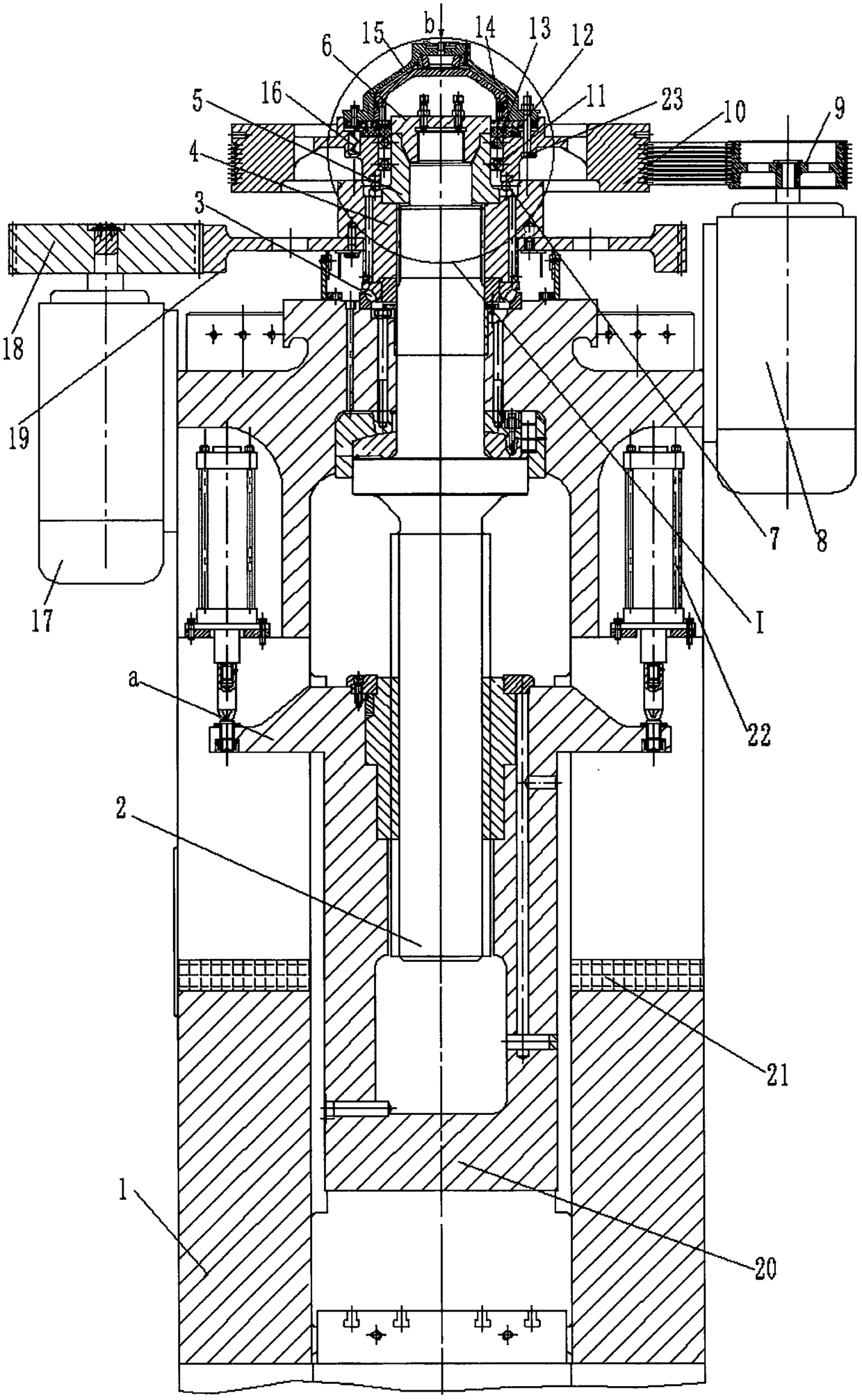
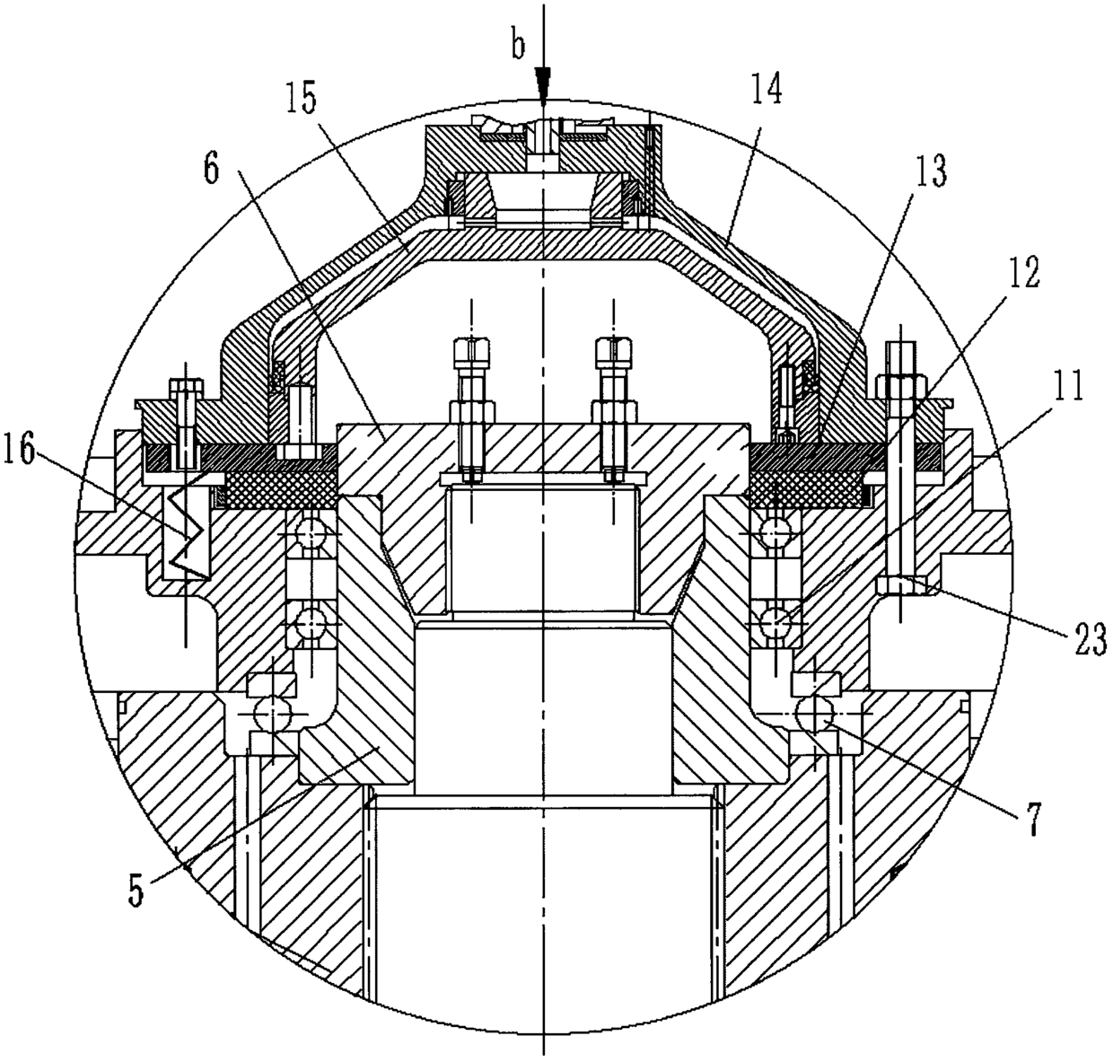
[0018] exist figure 1 , figure 2 Among them, the clutch and electric compound transmission type pneumatic screw press with bottom dead center of the present invention includes a fuselage 1, a screw rod 2 vertically installed through the inner hole of the upper beam of the fuselage, and installed on the upper plane groove of the upper beam of the fuselage The lower load-bearing bearing 3 in the groove is installed on the screw rod through threaded connection and pressed against the nut 4 on the upper end surface of the lower load-bearing bearing, the intermediate body 5 installed above the nut, and the nut gland 6 installed on the top of the screw rod above the intermediate body, The intermediate load bearing 7 installed in the plane groove on the nut, the main motor 8 installed on one side of the fuselage, the belt pulley 9 installed on the output shaft of the main motor, the large bearing installed on the upper part of the intermediate load bearing and driven by belt transmi...


PUM


Abstract

The invention provides a clutch-motor composite transmission type pneumatic screw press with a bottom dead center. The pneumatic screw press comprises a machine body, a screw rod, a lower carrying bearing mounted in a groove formed in the upper plane of a cross beam mounted on the machine body, a nut, an intermediate body, a nut gland, a middle carrying bearing, a main motor, a belt pulley, a big flywheel, an upper bearing, a friction plate, a friction disk type clutch, a pneumatic cylinder body, a cap-like annular piston, a reset spring, a reversible type reciprocating driving motor, a driving gear, a small flywheel, a sliding block, a bottom dead center buffer block mounted on a machine body base and balanced hoisting cylinders vertically mounted on the two sides of the machine body, and piston rods of the balanced hoisting cylinders are connected with extension bodies of the sliding block. The clutch-motor composite transmission type pneumatic screw press has the fixed bottom dead center and is reliable and safe in operation, friendly to environment and high in hitting speed. The die contact time is short. The die service life is long. The production efficiency is high. The unbalance load resistant capacity is high. Multi-position die forging is realized. The requirements for large energy and large hitting force are met. The clutch-motor composite transmission type pneumatic screw press can be extensively applied to the forging process of hot die forging forming.

Description

technical field [0001] The invention relates to a clutch and electric compound transmission type pneumatic screw press with a bottom dead point, which can be widely used in hot die forging forming forging technology. Background technique [0002] The existing screw press cannot meet the demand for large energy due to the small transmission ratio and short stroke. Generally, hydraulic control is adopted. If there is a deviation during processing, production and installation, it will cause oil leakage and other phenomena, endangering personal safety and causing environmental pollution. Secondly, because the equipment has no fixed bottom dead point, once the slider exceeds the bottom dead point during equipment use or maintenance, it will cause serious problems such as the separation of the screw and the slider, which will bring serious safety hazards to the equipment and staff. question. Contents of the invention [0003] The purpose of the present invention is to provide ...

Claims


Application Information

Patent Timeline
Patent Type & Authority Patents(China)
IPC IPC(8): B21J9/18B21J13/00B30B15/10B30B15/28
CPCB21J9/18B21J13/00B30B15/10B30B15/28
Inventor 贾元友
Owner 青岛浩源益友锻压机械有限公司
Learn More