
Grinder feed control system

A feed control and grinding machine technology, which is used in the control of workpiece feed movement, grinding machine parts, manufacturing tools, etc., can solve problems such as increased feed time, large safety distance, and reduced production and processing efficiency. , to achieve the effect of compressing processing time, ensuring safety and improving production efficiency

Inactive Publication Date: 2017-10-10
津上精密机床(浙江)有限公司
View PDF7 Cites 0 Cited by
  • Summary
  • Abstract
  • Description
  • Claims
  • Application Information

AI Technical Summary

Problems solved by technology

[0003] In the traditional grinding wheel feeding system, the safety distance is manually judged. When the grinding wheel is fast fed to the subjective safety distance, it starts to feed the workpiece slowly at a safe processing speed, and the safety distance judged by subjective consciousness is consistent with the The actual safety distance is relatively large, so that the feeding time is greatly increased; the processing time of a workpiece is a few seconds, and the slow feeding process in the entire feeding process takes 1-2 seconds, resulting in a large Reduced production and processing efficiency

Method used


Image

  • Grinder feed control system
  • Grinder feed control system
  • Grinder feed control system

Examples


Embodiment 1

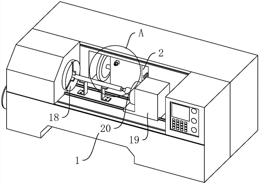
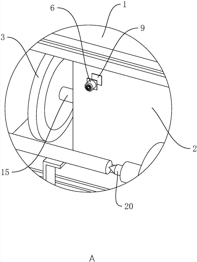
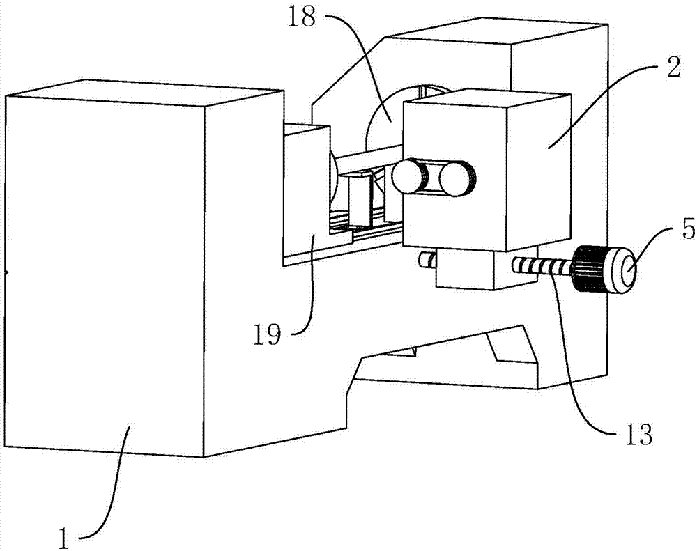
[0033] Embodiment 1: a grinding machine feed control system, such as figure 1 as shown in figure 1 , figure 2 , image 3 As shown, it includes a frame 1, a main shaft 18 and a tailstock 19 respectively arranged at both ends of the frame 1 in the length direction, a grinding wheel frame 2 slidingly connected to the frame 1 along the width direction of the frame 1, and a grinding wheel frame 2 connected to the grinding wheel through a bearing 15 in rotation. The grinding wheel 3 of frame 2, the grinding wheel motor 4 that controls the rotation of grinding wheel 3 through belt transmission (see Figure 4 ) and the servo motor 5 that controls the movement of the grinding wheel frame 2. The tailstock 19 is slidably connected to the frame 1 along the length direction of the frame 1. The tailstock 19 is fixed with a top 20 on the side facing the main shaft 18, and one end of the workpiece is clamped on the main shaft 18. Inside, the other end is fixed by the top 20, the lower end...

Embodiment 2

[0043] Embodiment 2: A grinding machine feed control system, such as Figure 7 , Figure 8 As shown, the difference from Embodiment 1 is that the AE sensor 6 is fixed on one side of the clamping piece 10 by bolts, and the cross section of the clamping piece 10 is I-shaped, on the side of the grinding wheel frame 2 close to the workpiece and close to the grinding wheel 3 A card slot 11 is vertically provided at one end of the card slot 10 to match the card slot 10, and the upper end of the card slot 11 is provided with an opening. on the frame 2; in order to prevent the clamping member 10 from falling out of the card slot 11, a rubber plug 12 with an interference fit with the card slot 11 is clamped at the opening of the upper end of the card slot 11, and the lower end of the rubber plug 12 is abutted against the card slot. The upper end of the connecting piece 10, so that the clamping piece 10 is firmly clamped in the slot 11, which facilitates the disassembly and assembly of...


PUM


Abstract

The invention discloses a grinder feed control system. The grinder feed control system comprises a rack, a grinding wheel frame, a grinding wheel, a grinding wheel motor and a servo motor, wherein the grinding wheel frame is slidably connected to the rack, the grinding wheel is rotationally connected to the grinding wheel frame, the grinding wheel motor controls the grinding wheel to rotate, and the servo motor controls the grinding wheel frame to move and is connected with a feed control system. The feed control system comprises a detection unit, an amplifier and a control module, wherein the detection unit is used for detecting a sound wave generated at the moment that the safe distance between the grinding wheel and a workpiece is achieved and outputting a sound wave detection signal, the amplifier is coupled with the detection unit and used for amplifying the sound wave detection signal and outputting a first close-control signal, and the control module is coupled with the amplifier and used for receiving and responding the first close-control signal to control the rotating speed of the servo motor. According to the grinder feed control system, the grinding wheel rapidly feeds within the safe range, accordingly the machining time is compressed, the production efficiency is improved, and the grinding wheel turns into slow feeding when close to the workpiece, so that machining safety is guaranteed.

Description

technical field [0001] The invention relates to the technical field of grinding machines, more specifically, it relates to a grinding machine feed control system. Background technique [0002] A grinding machine is a machine tool that uses abrasive tools to grind the surface of a workpiece. Most grinding machines use high-speed rotating grinding wheels for grinding. When grinding, the tool must be fed after the grinding wheel is balanced; and when the grinding wheel is fed, the feed rate should be correctly controlled; the grinding wheel cannot touch the workpiece at once, and a gap (safety distance) should be left, and then feed slowly. Avoid the rapid feeding of the grinding wheel directly touching the workpiece and causing the workpiece to pop up and hurt people, causing danger. [0003] In the traditional grinding wheel feeding system, the safety distance is manually judged. When the grinding wheel is fast fed to the subjective safety distance, it starts to feed the wor...

Claims


Application Information

Patent Timeline
Patent Type & Authority Applications(China)
IPC IPC(8): B24B49/00B24B49/14B24B47/20
CPCB24B47/20B24B49/003B24B49/006B24B49/14
Inventor 唐东雷
Owner 津上精密机床(浙江)有限公司
Features
  • Generate Ideas
  • Intellectual Property
  • Life Sciences
  • Materials
  • Tech Scout
  • Unparalleled Data Quality
  • Higher Quality Content
  • 60% Fewer Hallucinations
Learn More