Track distribution type electromagnetic induction charging device and charging method for underground tunnel

An electromagnetic induction and charging device technology, applied in circuit devices, electromagnetic wave systems, electrical components, etc., can solve the problems of high cost of accessories and construction, explosion, limited moving range, etc., achieve high power conversion efficiency, reduce battery capacity, low cost effect

Active Publication Date: 2012-10-10
SHENZHEN LAUNCH DIGITAL TECH
View PDF7 Cites 4 Cited by
  • Summary
  • Abstract
  • Description
  • Claims
  • Application Information

AI Technical Summary

Problems solved by technology

When the above three power supply methods are used in underground tunnels, they all have the defects that they cannot operate normally and safely: (1) For the power supply by tail-drag power supply cable, its main disadvantage is: the range of movement is limited, because the load of the rail car follows the track. As the load increases, the driving capacity of the track, the power supply cable, the rail car, the weight of the rail car, and the power consumption will all increase greatly, which will eventually lead to a significant decrease in the practicability under long distances; (2) for The main disadvantage of the trolley line and collector power supply method is that it cannot be explosion-proof, and there is a huge risk in mines, sewers and power tunnels, because combustible gases such as CO, CH4, and H2S may appear at any time in these places, and The unreliable connection power supply method of trolley line and collector may cause sparks and explosions due to poor contact; (3) For the current transformer induction power supply method, its

Method used


Image

  • Track distribution type electromagnetic induction charging device and charging method for underground tunnel
  • Track distribution type electromagnetic induction charging device and charging method for underground tunnel
  • Track distribution type electromagnetic induction charging device and charging method for underground tunnel

Examples


Embodiment Construction

[0030] Below in conjunction with accompanying drawing, the present invention is described in further detail:

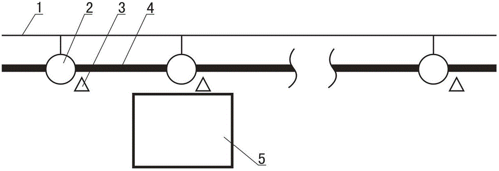
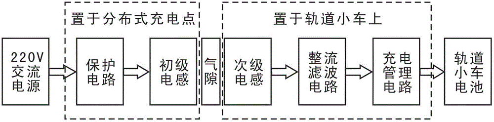
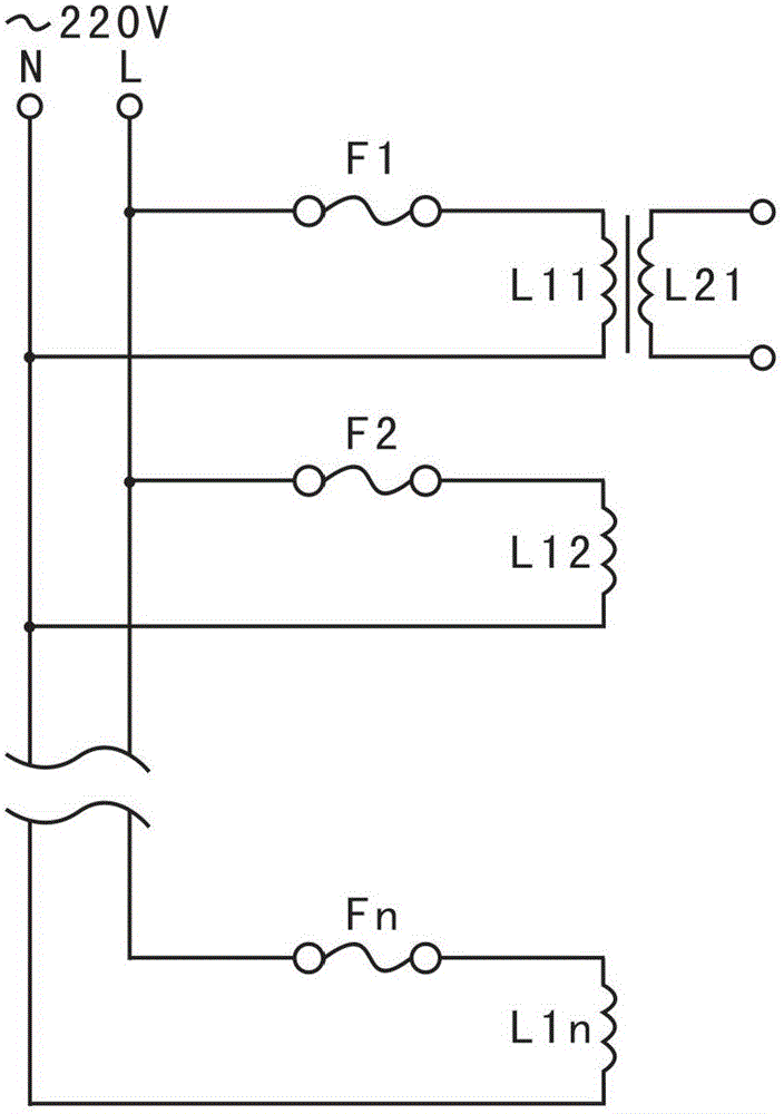
[0031] Such as figure 1 and figure 2As shown, the track distributed electromagnetic induction charging device for underground tunnels according to the present invention includes a protection circuit, a primary inductance 2, a secondary inductance, a rectification filter circuit, a charging management circuit, a positioning block 3, and an infrared emitting tube (Fig. not shown in the figure) and infrared receiving tube (not shown in the figure), the input end of the protection circuit is the input end of the AC power supply, which is connected to the AC wire 1, the output end of the protection circuit is connected to the input end of the primary inductor 2, and the primary inductor 2 and the secondary inductance are connected through electromagnetic induction, the output end of the secondary inductance is connected to the input end of the rectification filter circui...


PUM


Abstract

The invention discloses a track distribution type electromagnetic induction charging device for an underground tunnel. The track distribution type electromagnetic induction charging device comprises a plurality of protection circuits, a plurality of primary inductors, a secondary inductor, a rectification filter circuit and a charging management circuit, wherein an input end of each protection circuit is the input end of an alternating current power supply; the primary inductors and the secondary inductor are connected in an electromagnetic induction mode; an output end of the charging management circuit is a charging output end; a plurality of primary inductors are fixedly connected with a track in the underground tunnel respectively and arranged in sequence; and the secondary inductor, the rectification filter circuit and the charging management circuit are arranged in a vehicle to be charged. The invention also discloses a charging method. The charging method comprises the following steps of: acquiring a charging start signal; starting charging; performing constant-current charging; starting performing constant-current charging when the voltage of a battery is more than 14.4 V; and finishing charging when charging current is less than 0.05 A. By the invention, non-contact high-efficiency charging is realized, and an explosion safety accident caused by contacting charging sparks in the tunnel is avoided.

Description

technical field [0001] The invention relates to a charging device and a charging method for an underground tunnel, in particular to a track distributed electromagnetic induction charging device and a charging method for an underground tunnel. Background technique [0002] In many underground tunnels such as coal mines, sewers and power tunnels, there is an urgent need for some track-type video surveillance equipment with a large moving range. However, the power supply of mobile video monitoring equipment has become an obstacle that restricts this type of product from entering the practical stage. [0003] In the current track-mounted video surveillance equipment of this type, the power supply mainly has the following schemes: (1) Power supply by tail-drag power supply cable; (2) Power supply by trolley line and collector; (3) Power supply by current Transformer induction power supply. When the above three power supply methods are used in underground tunnels, they all have ...

Claims


Application Information

Patent Timeline
IPC IPC(8): H02J17/00H02J50/10
Inventor 宋晖鲜开义贾澄科杨莉君李金波
Owner SHENZHEN LAUNCH DIGITAL TECH
Why Eureka
Try Eureka