
Amplifying circuit comprising an envelope modulated limit cycles modulator circuit

A technology of amplifying circuit and periodic modulation, which is applied to amplifiers with semiconductor devices/discharge tubes, amplifiers, components of amplifiers, etc., can solve problems such as narrow operating bandwidth, and achieve the effect of large dynamic range

Inactive Publication Date: 2011-06-08
NXP BV
View PDF3 Cites 0 Cited by
  • Summary
  • Abstract
  • Description
  • Claims
  • Application Information

AI Technical Summary

Problems solved by technology

EER is limited to a narrow operating bandwidth due to the severe impact of path delay mismatch between the two signal processing paths

Method used


Image

  • Amplifying circuit comprising an envelope modulated limit cycles modulator circuit
  • Amplifying circuit comprising an envelope modulated limit cycles modulator circuit
  • Amplifying circuit comprising an envelope modulated limit cycles modulator circuit

Examples


Embodiment Construction

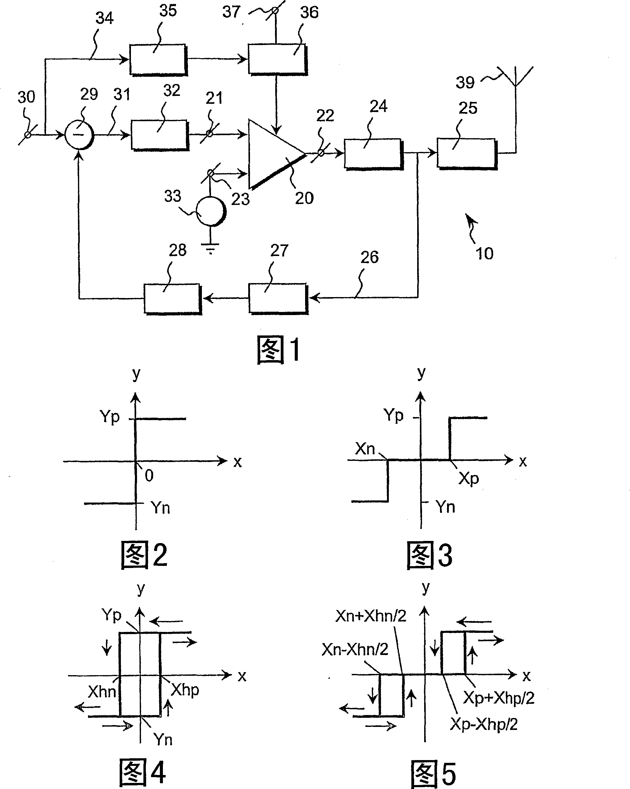
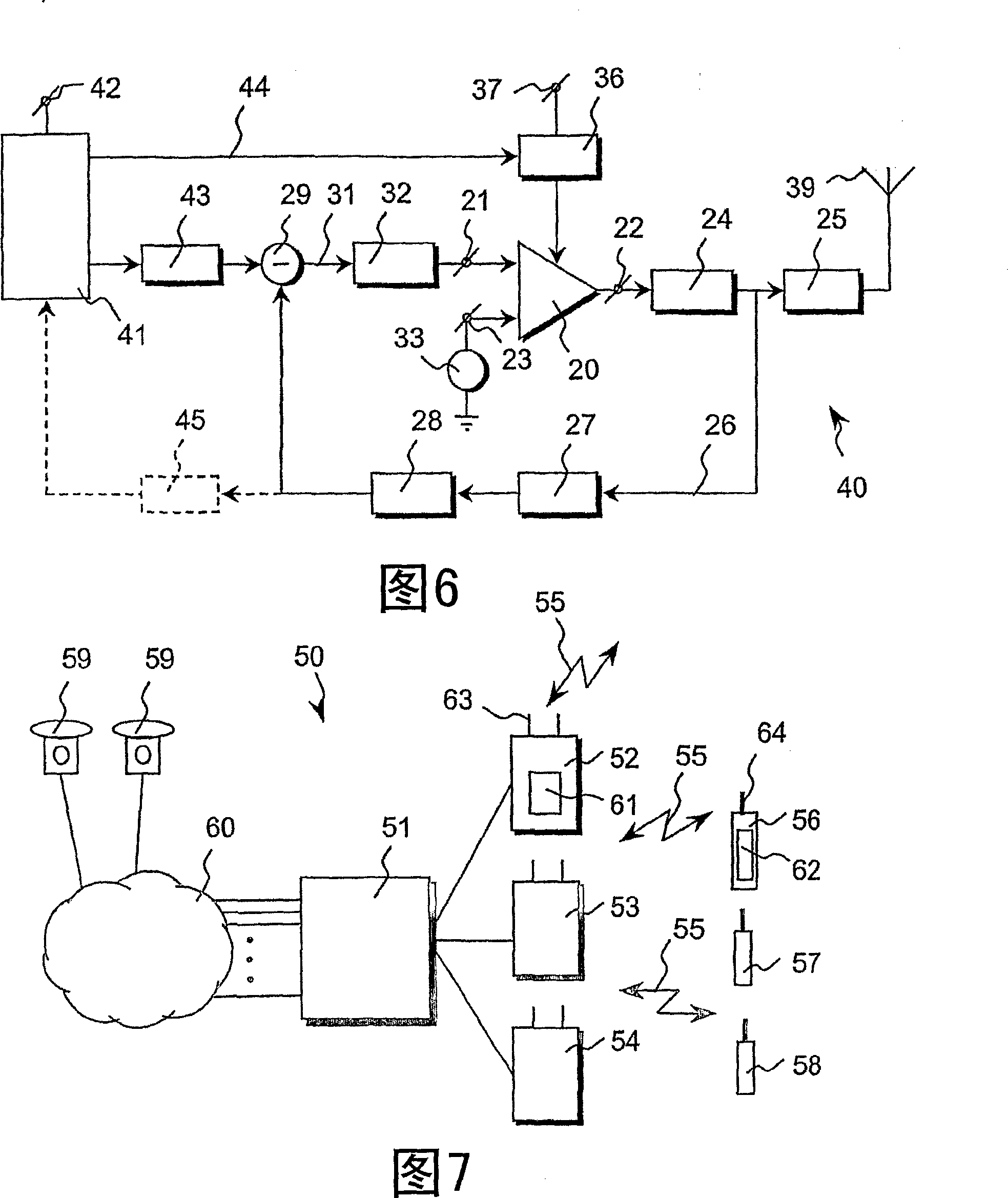
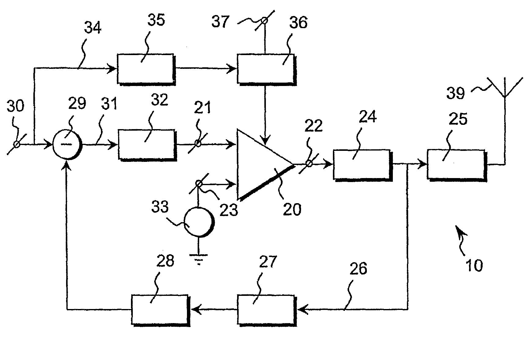
[0039] figure 1 A block diagram of a first general embodiment of an amplification circuit 10 according to the invention is shown. The main element of the circuit 10 is formed by a relay device 20 . The relay device 20 is a non-linear element for converting a modulated RF input signal applied at an input 21 of the relay device 20 to a discrete level output signal at an output 22 of the relay device 20 .

[0040] First filter means 24 and second filter means 25 are connected in series from output 22 of relay device 20 to a load in the form of antenna means 39 for transmitting the RF output signal generated at output 22 of relay device 20 . The antenna device 39 itself does not form part of the amplifier circuit 10 .

[0041] Optimally, the first filter means 24 may be configured for impedance matching of the relay device 20 in order to minimize reflection and transmission losses. Optimally, the second filter means 25 can be configured for RF band selection of the output sign...


PUM


Abstract

An amplifying circuit (10) for amplifying a modulated RF input signal, in particular for use in a radio transceiver circuit. The amplifying circuit (10) comprises a limit cycles modulator circuit (20-22, 26-29, 31-33), arranged for generating an amplified RF output signal from an RF input signal, and an envelope modulator circuit (34-36) arranged for amplitude modulating the RF output signal determined by envelope information extracted from the modulated input signal.

Description

technical field [0001] The present invention relates to the amplification of modulated radio frequency (RF) signals, particularly for use in radio transceiver circuits. Background technique [0002] The unprecedented demand for higher bandwidth efficiency in RF transmit systems has led to the use of complex modulation techniques, dealing with time-varying phase or frequency and amplitude signals. The use of these modulation techniques requires transceivers with very linear transmission characteristics in order to properly process the signal and suppress interference with adjacent channel transmissions. Maintaining linearity over a wide dynamic range is important for power amplifiers (PAs) utilizing power control. [0003] However, such a modulated signal contains a non-constant envelope, resulting in a relatively large envelope peak-to-average ratio. Therefore, conventional linear-mode PAs, such as Class A, Class AB, or Class B PAs, must operate in regions well below the 1...

Claims


Application Information

Patent Timeline
Patent Type & Authority Patents(China)
IPC IPC(8): H03F1/02H03F1/32H03F3/217
CPCH03F2200/331H03F1/3241H03F3/217H03F1/0222H03F1/02H03F1/32
Inventor 阿瑟·赫尔曼纳斯·马里亚·范勒尔蒙德约翰内斯·阿尔贝图斯·赫格特
Owner NXP BV
Learn More