Unlock instant, AI-driven research and patent intelligence for your innovation.

Transformer oil cooling system

A cooling system and transformer oil technology, applied in the field of transformers, can solve the problems of coil aging, explosion, and failure to achieve the effect of simple installation and high temperature control accuracy

Pending Publication Date: 2017-10-10
无锡威凯得精密机械有限公司
View PDF0 Cites 7 Cited by
  • Summary
  • Abstract
  • Description
  • Claims
  • Application Information

AI Technical Summary

Problems solved by technology

At present, most of the transformers operating on the power grid are still oil-immersed transformers. The usual oil-immersed transformers rely on the cooling fins arranged around the transformer to cool down the internal transformer oil. However, because the cooling fins are greatly affected by the environment, often When the ambient temperature is high, the expected effect cannot be achieved, which will cause major faults in the transformer. For example, due to the high oil temperature, the insulation performance of the transformer oil will decrease, the coil will age, and even the transformer will catch fire, explode and other accidents.

Method used


Image

  • Transformer oil cooling system
  • Transformer oil cooling system

Examples


Embodiment 1

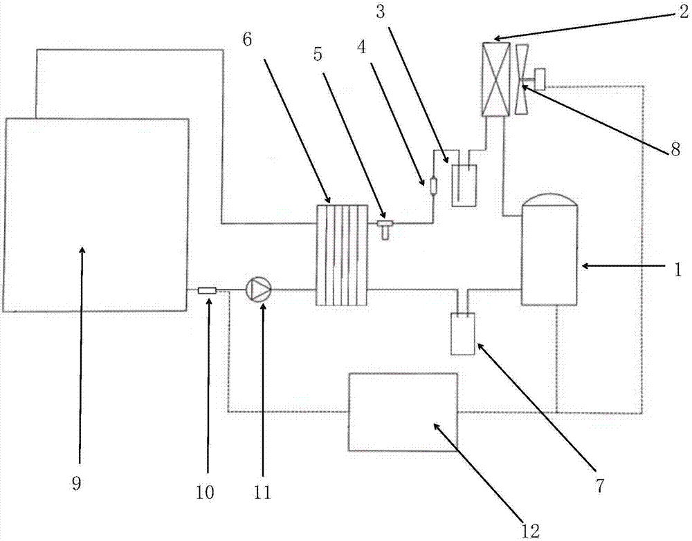
[0025] like figure 1 Shown:

[0026] Transformer oil cooling system, including: refrigeration system, forced oil circulation system and electric control system.

[0027] The refrigeration system includes: a refrigeration compressor 1, a finned condenser 2, a liquid storage cylinder 3, a dry filter 4, a thermal expansion valve 5, a plate evaporator 6, a gas-liquid separator 7 and a refrigeration pipeline.

[0028] The forced oil circulation system includes: oil-immersed transformer 9, circulating oil pump 11, plate evaporator 6 and oil pipeline.

[0029] The electronic control system includes: a temperature controller 12 and a temperature sensing element, that is, an oil temperature sensing element 10 .

[0030] Among them, the refrigeration compressor 1, the finned condenser 2, the liquid storage cylinder 3, the dry filter 4, the thermal expansion valve 5, the plate evaporator 6, and the gas-liquid separator 7 are sequentially connected through the refrigeration pipeline to ...

Embodiment 2

[0038] In order to further optimize the above scheme, such as figure 2 Shown:

[0039]The refrigeration system also includes: an air-cooled cooler arranged between the circulating oil pump 11 and the plate evaporator 6 in the forced oil circulation system, and an ambient temperature temperature measuring element 15 arranged in the environment outside the oil-immersed transformer. The cooler includes: a heat exchanger 13, and a cooling fan 14 matched therewith.

[0040] Embodiment 2 is designed in consideration of the energy-saving effect, and it is based on the device in Embodiment 1, and an air-cooled cooler is reinstalled in the oil circuit. The oil enters the main body of the heat exchanger through the oil pump. Since there are many cooling fins outside the oil channel of the heat exchanger, the cooling fan flows the surrounding cold air through the cooling fins, thereby reducing the temperature of the transformer oil in the oil flow channel.

[0041] Among them, refrige...


PUM


Abstract

The invention discloses a transformer oil cooling system, which includes: a refrigeration system, a forced oil circulation system and an electric control system; the refrigeration system includes a refrigeration compressor, a condenser, a liquid storage cylinder, a dry filter, an expansion device, an evaporator, Gas-liquid separator and refrigerating pipeline, the above-mentioned equipments are sequentially connected into a circular closed loop through the refrigerating pipeline; the forced oil circuit circulation system includes: oil-immersed transformer, circulating oil pump, evaporator and oil pipeline, and the above-mentioned equipment passes through the oil pipeline The electric control system includes a temperature sensing element and a temperature controller; the temperature controller is electrically connected with the temperature sensing element, a circulating oil pump, a refrigeration compressor and a condensing fan. The invention uses a refrigeration system to forcibly lower the temperature of the oil inside the transformer, and has the characteristics of simple installation and high temperature control accuracy, and can control the oil temperature and reduce faults even if the transformer is in a harsh environment.

Description

technical field [0001] The invention relates to the technical field of transformers, in particular to a transformer oil cooling system. Background technique [0002] Transformer is an important and indispensable power equipment in the transmission grid, which plays a vital role in regulating the voltage of the grid. Power transformers will generate core loss and winding loss during use, and these losses will cause the temperature of the core and winding to rise. In order to ensure the safe and reliable operation of the transformer, the winding temperature, iron core temperature and transformer oil temperature of the transformer need to be limited within the safe range, so the transformer needs to be radiated and cooled. At present, most of the transformers operating on the power grid are still oil-immersed transformers. The usual oil-immersed transformers rely on the cooling fins arranged around the transformer to cool down the internal transformer oil. However, because the...

Claims


Application Information

Patent Timeline
IPC IPC(8): H01F27/18H01F27/12H01F27/08H01F27/40
CPCH01F27/18H01F27/085H01F27/12H01F27/402H01F2027/406
Inventor 许勇莫春明
Owner 无锡威凯得精密机械有限公司