Flow control method for inhibiting surface cavitation phenomenons of underwater vehicle and hydrofoil

A surface cavitation and flow control technology, applied in the direction of hydrodynamic characteristics/hydrostatic characteristics, hull, hull design, etc., can solve the limited control effect of cavitation incipient phenomenon, increase weight, reduce hydrodynamic force and steering moment and other problems, to achieve the effect of eliminating cavitation flow phenomenon, reducing cavitation volume, and reducing retroreflection impact

Inactive Publication Date: 2017-10-13
HARBIN INST OF TECH
View PDF7 Cites 4 Cited by
  • Summary
  • Abstract
  • Description
  • Claims
  • Application Information

AI Technical Summary

Problems solved by technology

[0003] 1. Although the hydrodynamic shape optimization method can reduce or even eliminate the cavitation phenomenon at a certain sailing speed, in the actual sailing process, due to attitude changes or a slight increase in speed, cavitation will occur on the surface of the sailing body or hydrofoil. A local low-pressure cavitation area or even a large-scale cavitation area appears;
[0004] 2. The use of the isolation strip structure is mainly used to control the retroreflection and shedding of the cavitation, and the control effect on the incipient cavitation phenomenon is limited, and because the above isolation strip structure often protrudes from the surface of the vehicle or hydrofoil locally, thus There will be some additional resistance;
[0005] 3. The local groove structure will weaken the strength of the shell. In order to ensure its safety, the shell needs to be thickened, thereby increasing its weight, and because the groove structure can only adapt to specific flow conditions, when the sailing conditions change When , it is difficult to effectively

Method used


Image

  • Flow control method for inhibiting surface cavitation phenomenons of underwater vehicle and hydrofoil
  • Flow control method for inhibiting surface cavitation phenomenons of underwater vehicle and hydrofoil
  • Flow control method for inhibiting surface cavitation phenomenons of underwater vehicle and hydrofoil

Examples


Embodiment Construction

[0042] The technical solution of the present invention will be further described below in conjunction with the accompanying drawings, but it is not limited thereto. Any modification or equivalent replacement of the technical solution of the present invention without departing from the spirit and scope of the technical solution of the present invention should be covered by the present invention. within the scope of protection.

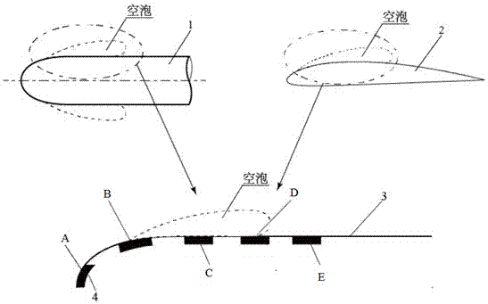
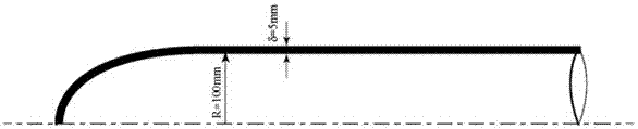
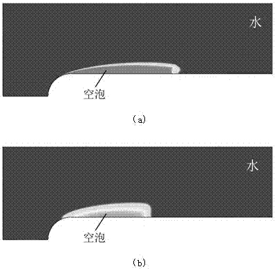
[0043] In order to eliminate or weaken the cavitation phenomenon on the surface of the vehicle and its hydrofoil, the present invention uses a porous medium material to cover or inlay the part of the vehicle or the hydrofoil and the entire surface of the solid wall. The porous medium material is made of alloy, ceramics, etc. The material has a fine pore structure inside, which can effectively suppress the cavitation flow phenomenon near the porous medium area or even the entire solid wall surface of the vehicle or hydrofoil. Specific implementation plan...


PUM


Abstract

The invention discloses a flow control method for inhibiting surface cavitation phenomenons of an underwater vehicle and a hydrofoil. The method comprises the steps that porous medium materials are adopted and fixed to the local or total fixing wall surface of the underwater vehicle or the hydrofoil, and the specific fixing position is one of the following situations: A, the porous medium materials are fixed to the upstream region of the primary cavitation position of the fixing wall surface of the underwater vehicle or the hydrofoil; B, the porous medium materials are fixed to the neighborhood of the primary cavitation position of the fixing wall surface of the underwater vehicle or the hydrofoil; C, the porous medium materials are fixed to the corresponding cavitation region of the fixing wall surface of the underwater vehicle or the hydrofoil; D, the porous medium materials are fixed to the corresponding cavitation tail portion and the neighborhood region of the fixing wall surface of the underwater vehicle or the hydrofoil; E, the porous medium materials are fixed to the corresponding cavitation tail downstream region of the fixing wall surface of the underwater vehicle or the hydrofoil. According to the flow control method, the cavitation flow phenomenons of the porous medium neighborhood even the fixing wall surface of the whole underwater vehicle or the hydrofoil are effectively inhibited.

Description

technical field [0001] The invention relates to a flow control method for suppressing cavitation, in particular to a flow control method for suppressing the cavitation phenomenon on the surface of an underwater vehicle and a hydrofoil. Background technique [0002] In order to control the cavitation phenomenon on the surface of the vehicle or hydrofoil to achieve the purpose of improving the hydrodynamic characteristics of the vehicle, improving its structural reliability and reducing flow noise, the existing cavitation suppression technologies mainly include: hydrodynamic shape optimization, local roughness Surfaces, barrier strip structures and jets. The above cavitation suppression technologies all have certain problems: [0003] 1. Although the hydrodynamic shape optimization method can reduce or even eliminate the cavitation phenomenon at a certain sailing speed, in the actual sailing process, due to attitude changes or a slight increase in speed, cavitation will occur...

Claims


Application Information

Patent Timeline
IPC IPC(8): B63B1/32
CPCB63B1/32Y02T70/10
Inventor 刘华坪于永川
Owner HARBIN INST OF TECH
Why Eureka
Try Eureka