Two-way circulation sweep-type multifunctional sweeper

A two-way circulation, drag-sweeping technology, applied in the field of sanitation cleaning vehicles, can solve the problems of high manufacturing cost, low cleaning force, and easy generation of dust.

Pending Publication Date: 2017-10-13
苟振庆
View PDF0 Cites 3 Cited by
  • Summary
  • Abstract
  • Description
  • Claims
  • Application Information

AI Technical Summary

Problems solved by technology

Suction-sweeping sweepers are high-energy-consuming products with low sweeping power. They are only suitable for cleaning fine dust, and their use is limited to wide road surfaces. The main technology is suction. The design of this technology is complicated, and its manufacturing cost is very high.
The main technology of the pure-sweeping sweeper is to throw the garbage into the trash can by rotating the roller brush. This technology is simple in design, and the cleaning force, cleaning height, and garbage capacity are all limited. Moreover, the cleaning is not clean, and it is easy to generate dust and cause secondary pollution. Pollution
The main technology of the low-high combined sweeper is towing and sweeping. Its disadvantage is that it cannot effectively clean the granular garbage and fine dust at the same time, so it is difficult to transform it into productivity.
Therefore, the current cleaning vehicle machinery cannot be fully utilized, resulting in the modern cleaning business mainly relying on manual work and large brooms, which is still in a backward and primitive state.

Method used


Image

  • Two-way circulation sweep-type multifunctional sweeper

Examples


Embodiment Construction

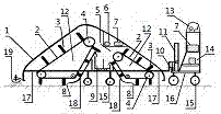
[0006] As can be seen from this figure, the present invention is a special cleaning vehicle for environmental sanitation. It is composed of cleaning devices 12 located in different directions on the same horizontal line, a garbage loading box 1, and a power electromechanical driving mechanism, combined and optimized, and then installed with auxiliary electric cleaning. 19, designed as a whole body. Wherein: cleaning device 12 it is made up of three axle rollers 4 that cross section forms obtuse angle triangle, wide leather conveyer belt 2, cleans board surface brush 3 to form, and wherein in the obtuse angle triangle that cross section forms, the side corresponding to an acute angle is close to the ground, around three shafts The roller 4 is equipped with a wide-skinned conveyor belt 2, on the wide-skinned conveyor belt 2 there are several cleaning panel brushes 3 arranged substantially parallel to the three shafted rollers 4, and the three shafted rollers 4 are fixed on the in...


PUM


Abstract

The invention discloses a two-way circulation sweep-type multifunctional sweeper. The two-way circulation sweep-type multifunctional sweeper is an environmental sanitation special sweeper with the integrated functions of conducting running, sweeping and loading. The sweeper is an overall mechanism formed through the design of a sweeping device 12, a rubbish loading box 1, a power electromechanical walking mechanism, and an auxiliary electric sweeping side brush 19, wherein the sweeping device 12, the dustbin loading box 1, the power electromechanical walking mechanism and the auxiliary sweeping side brush 19 are in the same horizontal line and different directions. The sweeping device 12 is composed of three shaft rollers 4, a wide leather conveyor belt 2 and a sweeping board brush 3. The rubbish loading box 1 mainly comprises a dustbin 9, a rubbish baffle 5, a rubbish slide plate 18, and an elastic bottom-touch floor 8. The power electromechanical walking mechanism is mainly composed of a sweeping electromechanical unit 6, a walking electromechanical unit 14, an energy source 7, a vehicle frame 17, a chassis 16, vehicle wheels 15, a lifting device, a driving operating system 13 and the like. The specifications and the model numbers of the two-way circulation sweep-type multifunctional sweeper can be designed according to work needs and the magnitude of power, the application range is wide, the manufacturing cost is low, low energy is consumed in sweeping, and the two-way circulation sweep-type multifunctional sweeper is efficient and raises no dust, and has functions of sweeping rubbish, dust and snow, and draining water.

Description

technical field [0001] The invention relates to a sanitation cleaning vehicle, in particular to a modern two-way cycle mopping and sweeping multifunctional cleaning vehicle. Background technique [0002] At present, the cleaning technologies of cleaning vehicle machinery in the international and domestic markets are mainly two types of suction sweeping and pure sweeping, and there are also low-high combined sweeping vehicle technologies that have not been transformed into] productivity. Suction-sweeping sweepers are high-energy-consuming products with low cleaning power. They are only suitable for cleaning fine dust, and their use is limited to wide road surfaces. The main technology is suction. This technology is complex in design and very expensive to manufacture. The main technology of the pure-sweeping sweeper is to throw the garbage into the trash can by rotating the roller brush. This technology is simple in design, and the cleaning force, cleaning height, and garbage ...

Claims


Application Information

Patent Timeline
Patent Type & Authority Applications(China)
IPC IPC(8): E01H1/04
CPCE01H1/04E01H1/042E01H1/047
Inventor 不公告发明人
Owner 苟振庆
Why Eureka
Try Eureka