Cylindrical air intake and exhaust device and internal combustion engine cylinder cover

A technology for intake and exhaust and internal combustion engines, applied to valve devices, cylinder heads, engine sealing devices, etc., can solve problems such as reducing the stroke of work, and achieve the effects of reducing energy, reducing weight, and improving efficiency

Pending Publication Date: 2017-10-13
夏周旋
View PDF14 Cites 1 Cited by
  • Summary
  • Abstract
  • Description
  • Claims
  • Application Information

AI Technical Summary

Problems solved by technology

This is to use the higher gas pressure in the cylinder to make the exhaust gas flow out of the cylinder automatically, so that the gas pressure in the cylinder is lower when the piston moves from the bottom dead center to the top dead center, so as to reduce the work consumed by the piston to expel the exhaust gas out of the cylinder. This also reduces the work travel

Method used


Image

  • Cylindrical air intake and exhaust device and internal combustion engine cylinder cover
  • Cylindrical air intake and exhaust device and internal combustion engine cylinder cover
  • Cylindrical air intake and exhaust device and internal combustion engine cylinder cover

Examples


Embodiment 1

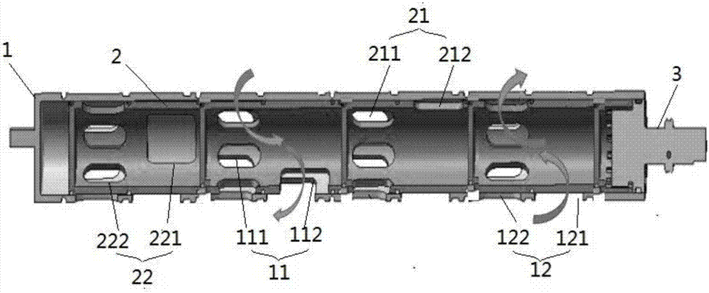
[0053] Such as figure 1 As shown, this embodiment provides a cylinder-type air intake and exhaust device, which includes an outer cylinder 1 , an inner cylinder 2 and a drive shaft 3 . The outer cylinder 1 is cylindrical with one end open, and the outer cylinder 1 is provided with an outer cylinder air intake hole group 11 and an outer cylinder exhaust hole group 12 . The inner cylinder 2 is cylindrical and is rotatably installed in the cavity of the outer cylinder 1. The inner cylinder 2 can be loaded into the outer cylinder 1 from the open end of the outer cylinder 1. The inner cylinder 2 is provided with an inner cylinder air inlet group 21 and an inner cylinder. Barrel vent group 22. The drive shaft 3 is connected to the inner cylinder 3 to drive the inner cylinder 3 to rotate. This structure can significantly reduce the size and weight of the entire internal combustion engine.

[0054] The sweeping surface of the air intake hole group 21 of the inner cylinder overlaps ...

Embodiment 2

[0070] For larger internal combustion engines, such as diesel engines, in order to facilitate manufacturing and installation, such as Figure 8 As shown, the cover body 4 can be made separately, and the cover body is divided into an upper cover 45 and a lower cover 46. When assembling, the upper cover 45 and the lower cover 46 are fixedly connected by bolts. The intake part and the exhaust part of the internal combustion engine can also be provided separately, and the upper cover 45 is provided with the semicircular groove 511 of the intake and the semicircular groove 521 of the exhaust, and the lower cover 46 is provided with the semicircular groove 521 of the intake. Shaped groove 512 and semicircular groove 522 for exhaust. After the upper cover 45 and the lower cover 46 are combined, the semicircular groove 511 and the semicircular groove 512 form the intake cavity 51 , and the semicircular groove 512 and the semicircular groove 522 form the exhaust cavity 52 . The intake...


PUM


Abstract

The invention discloses a cylindrical air intake and exhaust device and an internal combustion engine cylinder cover. The cylindrical air intake and exhaust device comprises an outer cylinder, an inner cylinder, and a driving shaft. The outer cylinder is in the shape of a cylinder having an opening, and the outer cylinder is provided with an outer cylinder air intake hole group and an outer cylinder air exhaust hole group. The inner cylinder is in the shape of a cylinder, and is rotatably disposed in the cavity of the outer cylinder. The inner cylinder is provided with an inner cylinder air intake hole group and an inner cylinder air exhaust hole group. The swept area of the inner cylinder air intake hole group is superposed with the outer cylinder air intake hole group, and the swept area of the inner cylinder air exhaust hole group is superposed with the outer cylinder air exhaust hole group. The driving shaft is connected with the inner cylinder, and is used to drive the inner cylinder to rotate and move axially. The internal combustion engine cylinder cover has the cylindrical air intake and exhaust device. By adopting the cooperation between the cylindrical air intake and exhaust device and the cover body, the weights of the air exhaust device and the cylinder cover are reduced, the performance and the efficiency of the internal combustion engine are greatly improved, and production costs are reduced.

Description

technical field [0001] The invention belongs to the technical field of mechanical equipment, and in particular relates to a cylinder type intake and exhaust device and a cylinder head of an internal combustion engine. Background technique [0002] The internal combustion engine includes a cylinder head and a cylinder block. The cylinder head, the cylinder block and the piston form a closed cylinder. The piston can reciprocate in the cylinder body, and the piston drives the crankshaft to rotate to provide power for external equipment. The working process of an internal combustion engine includes intake, compression, power and exhaust four strokes. [0003] During the intake stroke, the piston is at the top dead center, the intake valve opens, the exhaust valve closes, and the gas enters the cylinder through the intake valve. During the compression stroke, the gas in the cylinder is compressed, the pressure increases and the temperature rises. During the power stroke, fuel i...

Claims


Application Information

Patent Timeline
Patent Type & Authority Applications(China)
IPC IPC(8): F01L1/00F02F1/42
CPCF01L1/00F02F1/4285F01L1/34F01L7/026F01L7/027F01L13/00F01L13/06F01L2001/34496F01L2013/001F01L2250/02F01L2250/04F01L2800/01F01L2820/01F01L2820/042F01L2820/043F01L2820/044F01L2820/04F01L2001/0537Y02T10/12F02F2001/244F02F1/243F02F11/002F02F1/4264
Inventor 夏周旋崔易声夏春光夏博文
Owner 夏周旋
Why Eureka
Try Eureka