
Machining method for multi-gear

A technology of multi-stage gears and processing methods, applied in the processing of gears and multi-stage gears, can solve the problems of high noise, non-concentricity of multi-stage gears, and short service life, so as to eliminate mechanical internal stress and avoid welding deformation. , the effect of prolonging the service life

Inactive Publication Date: 2017-10-17
燕凌飞
View PDF5 Cites 5 Cited by
  • Summary
  • Abstract
  • Description
  • Claims
  • Application Information

AI Technical Summary

Problems solved by technology

[0003] As the basic element of gear transmission, the gear is a mechanical element with teeth on the wheel rim that can continuously mesh to transmit motion and power. At present, the structure of the single ring gear is the best and the easiest to process. Any kind of tooth shape processing method can be used. Machining the wheel part, and for multi-ring multiple gears such as double or triple, it usually consists of a pinion and one or more large gears sleeved on the outside of the pinion, and the pinion usually includes an inner hole for installing the gear shaft , the inner hole of the pinion usually includes a middle inner hole and end inner holes arranged at both ends of the middle inner hole. The processing of the ring tooth shape is usually difficult to machine because of its shape and position, and usually only the processing method of gear shaping can be used
[0004] However, the processing accuracy of gear shaping is far lower than that of grinding gears. Therefore, the processing method of multiple gears widely used at present is to firstly carry out fine grinding of the large and small gear blanks with split structure, and then weld them after assembly. It is fixed and connected as an integrated structure. The multi-connected gears processed by this method of assembly after finishing and welding and fixing are not only easy to cause misalignment due to welding deformation, but also the internal stress of welding cannot be removed. At the same time, the simple fine grinding There is still mechanical internal stress in the teeth, so it is easy to cause poor meshing conditions of multiple gears, resulting in high noise and short service life

Method used


Image

  • Machining method for multi-gear

Examples


Embodiment Construction

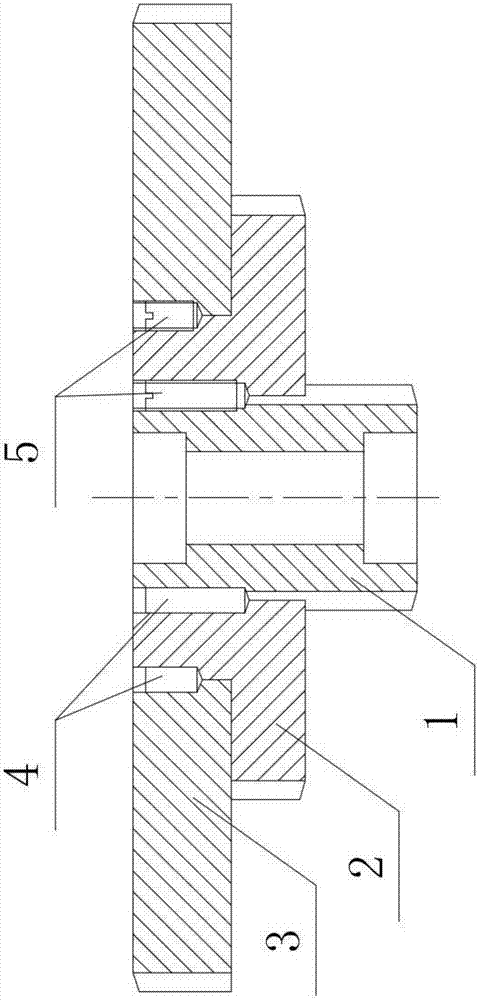
[0024] The present invention will be further described below by taking the triple gear as an example in conjunction with the accompanying drawings.

[0025] Such as figure 1 Shown, the processing method of this multi-connected gear comprises the following steps:

[0026] a. Blanking: According to the size required by the process, the blanks of the small gear 1, the second-stage large gear 2, and the third-stage large gear 3 are blanked;

[0027] b. Forging heat treatment: According to the size required by the process, the blanks of the pinion gear 1, the second-stage bull gear 2, and the third-stage bull gear 3 are forged and formed into blanks, then quenched, and finally tempered;

[0028] c. Turning processing: According to the size required by the process, turn the outer diameters of the pinion 1, the second-stage large gear 2, and the third-stage large gear 3 to the size of the addendum circle grinding process, and the pinion 1 and the second-stage large gear 2. The inne...


PUM


Abstract

The invention discloses a processing method of a multi-link gear, which comprises the steps of blanking, forging heat treatment, turning processing, inner hole grinding, tooth processing, shot peening treatment, fine grinding of the tooth and the like. The processing method of this multi-link gear adopts the method of hole positioning, and realizes the matching installation and connection between the small gear and each large gear through positioning pins and set screws, so the coaxiality is effectively guaranteed, and better processing accuracy is achieved. , so as to achieve better meshing conditions for multiple gears and reduce meshing noise; because welding is not used for connection, welding deformation and welding internal stress can be avoided; because shot peening is carried out before fine grinding, it can eliminate The mechanical internal stress of the rough machining of the teeth, thereby prolonging the service life of the multiple gears.

Description

technical field [0001] The invention relates to a gear processing method, in particular to a multi-connected gear processing method, and belongs to the technical field of gear machining. Background technique [0002] Gear transmission is the most widely used form of transmission in mechanical transmission. Because of its characteristics of accurate transmission ratio, high efficiency, compact structure, reliable operation and long life, it is widely used in modern machine tools and instruments. [0003] As the basic element of gear transmission, the gear is a mechanical element with teeth on the wheel rim that can continuously mesh to transmit motion and power. At present, the structure of the single ring gear is the best and the easiest to process. Any kind of tooth shape processing method can be used. Machining the wheel part, and for multi-ring multiple gears such as double or triple, it usually consists of a pinion and one or more large gears sleeved on the outside of th...

Claims


Application Information

Patent Timeline
Patent Type & Authority Applications(China)
IPC IPC(8): B23P15/14
CPCB23P15/14
Inventor 燕凌飞
Owner 燕凌飞
Learn More