Multi-functional heat pump drying device

A technology of heat pump drying and heat pump device, applied in drying, heat pump, dryer and other directions, can solve the problems of low drying efficiency, defective adaptability, uneconomical energy consumption cost of condensation and dehumidification, etc., to achieve easy product operation , the effect of simple structure

Pending Publication Date: 2017-10-17
广东华天成新能源科技股份有限公司
View PDF6 Cites 2 Cited by
  • Summary
  • Abstract
  • Description
  • Claims
  • Application Information

AI Technical Summary

Problems solved by technology

[0002] Heat pumps have the energy-saving effect of high-efficiency heating, and at the same time have the characteristics of generating cooling capacity while heating. Therefore, heat pumps have been widely used in the field of drying and dehumidification. At present, heat pump drying equipment is mainly divided into individual functions with waste heat recovery. There are two types of hot air function and hot air belt dehumidification function. The former has the advantages of simple structure and high heating energy efficiency. However, this technology is not effective in dealing with low-temperature drying in high humidity environments. The high relative humidity of the environment causes low drying efficiency, and the latter has the advantage of outputting hot air with a lower dew point, which can realize rapid drying of materials at a lower temperature using air with a lower relative humidity, but the disadvantage of this technology is that when When the moisture content of the material is low, the sensible heat energy consumption of the dehumidification surface cooler greatly exceeds the dehumidification energy consumption, especially in the high temperature and low humidity working conditions, the excessive energy consumption of condensation dehumidification is obviously not cost-effective
According to the above analysis, the single hot air technol

Method used


Image

  • Multi-functional heat pump drying device
  • Multi-functional heat pump drying device
  • Multi-functional heat pump drying device

Examples


Embodiment Construction

[0028] The present invention will be further described below in conjunction with the accompanying drawings and embodiments.

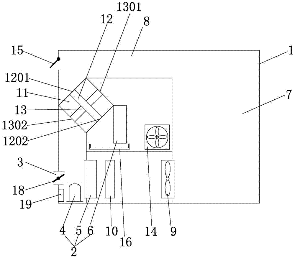
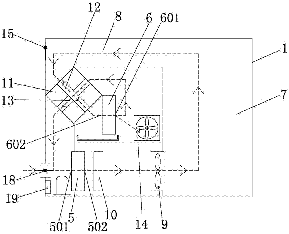
[0029] Such as figure 1 As shown, a multifunctional heat pump drying device includes a drying chamber 1 and a heat pump device 2. The drying chamber 1 is provided with a fresh air inlet 3, and the heat pump device 2 includes a compressor 4, a condenser 5 and an evaporator 6. The The drying chamber 1 is provided with a drying area 7 and a return air area 8, the air inlet end 501 of the condenser 5 is adjacent to the fresh air inlet 3, and the air outlet end 502 of the condenser 5 is connected to the drying area through the internal circulation fan 9. 7 is connected, and an electric heater 10 is installed between the condenser 5 and the internal circulation fan 9;

[0030] The role of the electric heater is to provide auxiliary heat supply during the cold start stage to speed up the temperature rise. It is a backup heat source, especially suitable for us...


PUM


Abstract

A multi-functional heat pump drying device comprises a drying chamber and a heat pump unit. A fresh air inlet is formed in the drying chamber, and the heat pump unit comprises a compressor, a condenser and an evaporator; a drying area and an air return area are arranged in the drying chamber, and the air inlet end of the condenser is arranged next to a fresh air inlet; the air outlet end of the condenser communicates with the drying area through an inner circulation draught fan; the multi-functional heat pump drying device further comprises a sensible heat exchanger which internally comprises a first air inlet, a first air outlet, a second air inlet and a second air outlet, hot air discharged from the air outlet end of the condenser passes through the drying area and the air return area successively, and then the air outlet end of the condenser communicates with the first air inlet; the first air outlet communicates with an air inlet of the evaporator, and an air outlet of the evaporator communicates with the second air inlet; the drying chamber of one side of the air outlet of the evaporator is provided with a cold air exhauster, and the second air outlet communicates with the air inlet end of the condenser; the drying chamber of one side of the air return area is provided with a hot air exhausting door; and the most suitable working mode is automatically selected under different working conditions, and product operation is easy.

Description

technical field [0001] The invention relates to the field of heat pump drying equipment, in particular to a multifunctional heat pump drying device. Background technique [0002] Heat pumps have the energy-saving effect of high-efficiency heating, and at the same time have the characteristics of generating cooling capacity while heating. Therefore, heat pumps have been widely used in the field of drying and dehumidification. At present, heat pump drying equipment is mainly divided into individual functions with waste heat recovery. There are two types of hot air function and hot air belt dehumidification function. The former has the advantages of simple structure and high heating energy efficiency. However, this technology is not effective in dealing with low-temperature drying in high humidity environments. The high relative humidity of the environment causes low drying efficiency, and the latter has the advantage of outputting hot air with a lower dew point, which can real...

Claims


Application Information

Patent Timeline
IPC IPC(8): F26B21/00F26B21/08F26B25/00F25B30/02
CPCF25B30/02F26B21/002F26B21/086F26B25/00
Inventor 郭建毅林建东胡书雄
Owner 广东华天成新能源科技股份有限公司
Why Eureka
Try Eureka