
Intelligent home control system and method

A technology of smart home control and control method, applied in general control system, control/regulation system, program control and other directions, can solve the problems of high product price, high system price, complex chip manufacturing process, etc. The effect of low cost and simple product operation

Inactive Publication Date: 2014-04-02
NINGBO JIANGBEI POTEK ELECTRONICS & TECH CO LTD
View PDF4 Cites 12 Cited by
  • Summary
  • Abstract
  • Description
  • Claims
  • Application Information

AI Technical Summary

Problems solved by technology

Most of the current smart home systems are implemented using WIFI, ZigBee, Bluetooth, KNX, X10 and other technologies. These technologies are all complicated and huge agreements formulated by industry alliances or interest groups, resulting in complex chip manufacturing processes and cost Expensive, suitable for wireless transmission of large data, or high confidentiality data transmission
When a modular circuit of this type of technology is placed in each electrical device, the price of the entire system will inevitably be high, and the realization of a single control action requires multiple protocols to be reviewed, which will inevitably lead to complicated operations.
[0004] The control of electrical equipment in most home life is simply ON and OFF, or light adjustment, speed adjustment and other actions, and does not require a very high level of confidentiality operation, and the data transmission rate is not required to be higher than 10Kbit / S, WIFI , ZigBee, Bluetooth, KNX, X10 and other technologies, the wireless transmission rate is much higher than this requirement, so the wasteful use of technology leads to expensive products and complicated operations

Method used


Image

  • Intelligent home control system and method
  • Intelligent home control system and method
  • Intelligent home control system and method

Examples


Embodiment Construction

[0028] The present invention will be further described in detail below in conjunction with the accompanying drawings and embodiments.

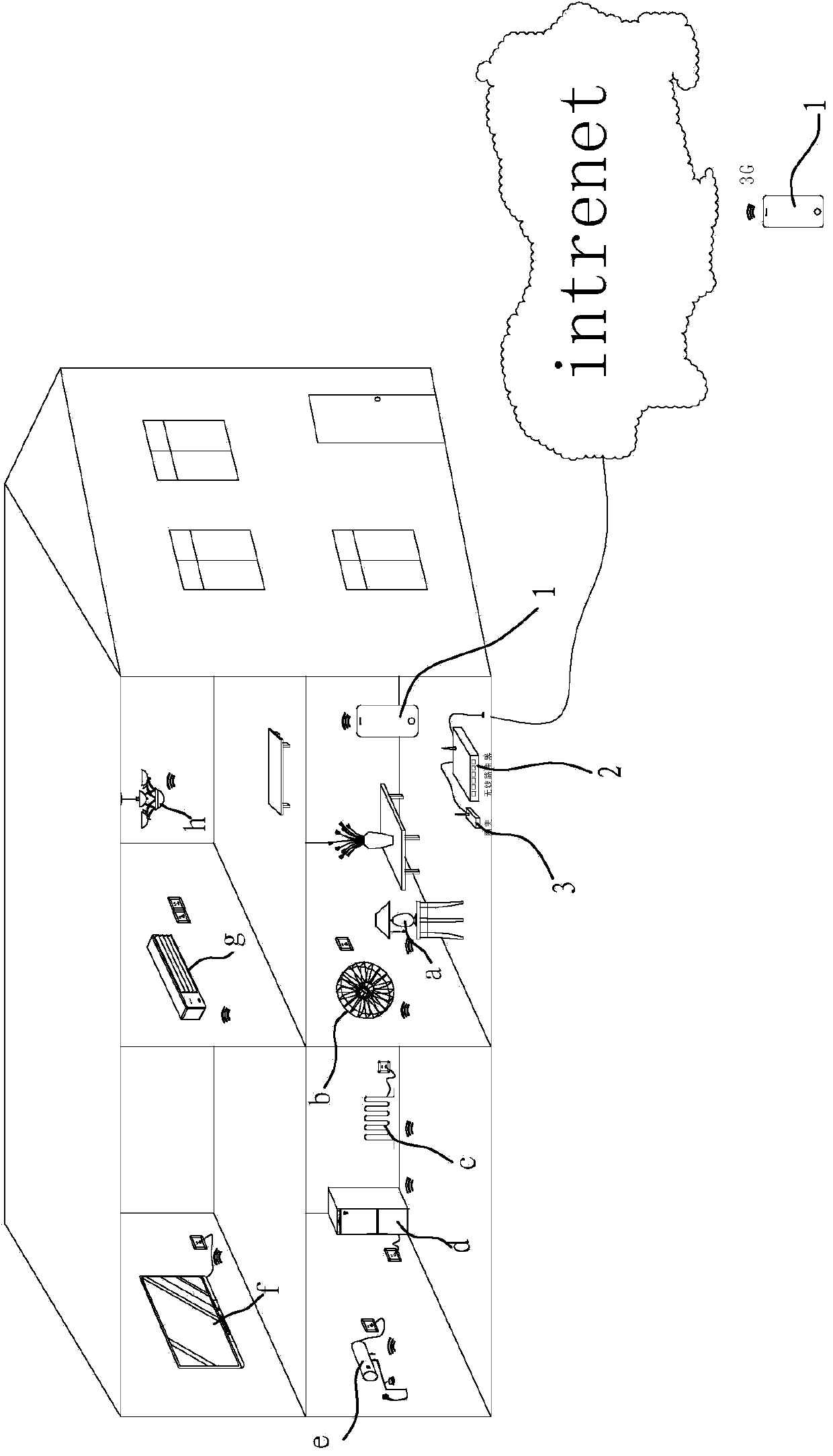
[0029] Such as figure 1 The smart home control system shown includes:

[0030] Multiple household electrical equipment, such as table lamp a, electric fan b, electric heater c, refrigerator d, electric water heater e, TV f, air conditioner g, ceiling fan h, etc.

[0031] The control terminal 1 can send control signals for controlling the working status of household electrical equipment. The control terminal here is a smart phone or other smart mobile terminal installed with furniture intelligent control software;

[0032] Wireless router 2, the control terminal is connected to the wireless router through a wireless network, where the wireless network can be a mobile network or WIFI;

[0033] The gateway 3 is wired with the wireless router 2, and the wireless router forwards the control signal sent by the control terminal to the gateway, and ...


PUM


Abstract

The invention relates to an intelligent home control system, which comprises home electric equipment. The intelligent home control system is characterized in that the intelligent home control system additionally comprises a control terminal, a wireless router and a gateway, the control terminal can transmit control signals for controlling the working states of the home electric equipment; the control terminal is connected with the wireless router through a wireless network; the gateway is connected with the wireless router, the wireless router forwards the control signals transmitted by the control terminal to the gateway, the gateway comprises an MCU (Micro Control Unit) circuit which is used for recognizing and decoding the control signals transmitted by the control terminal, and a first radio-frequency transceiver module which is connected with the MCU circuit and is used for realizing the wireless radio-frequency transmission of the decoded control signals; a second radio-frequency transceiver module which can receive the control signals transmitted by the first radio-frequency transceiver module is installed on the home electric equipment. The entire system is very low in cost and is very economical and applicable.

Description

technical field [0001] The invention relates to a smart home control system and a control method. Background technique [0002] After the popularity of smart phones and other smart mobile terminals, various smart home systems have emerged, which facilitate the daily life of the public. [0003] However, most smart home control systems are expensive and complicated to operate, which makes ordinary consumers daunted. The reason is that designers have realized many simple requirements in home life through complex technologies. Most of the current smart home systems are implemented using WIFI, ZigBee, Bluetooth, KNX, X10 and other technologies. These technologies are all complicated and huge agreements formulated by industry alliances or interest groups, resulting in complex chip manufacturing processes and cost Expensive, suitable for wireless transmission of large data, or high confidentiality data transmission. When a modular circuit of this type of technology is placed in...

Claims


Application Information

Patent Timeline
IPC IPC(8): G05B19/418
CPCG08C17/02G05B19/0423G05B2219/23297G05B2219/25167G05B2219/2642G08C2201/40G08C2201/50
Inventor 秦兵
Owner NINGBO JIANGBEI POTEK ELECTRONICS & TECH CO LTD
Features
  • Generate Ideas
  • Intellectual Property
  • Life Sciences
  • Materials
  • Tech Scout
  • Unparalleled Data Quality
  • Higher Quality Content
  • 60% Fewer Hallucinations
Learn More