Photovoltaic micro-network-system off-grid/grid-connected control method based on inverse droop control

A control method and photovoltaic technology, applied in photovoltaic power generation, AC network circuits, single-network parallel feeding arrangements, etc., can solve the problem that the grid-connected current waveform cannot reach the ideal state, the output current of the inverter cannot be directly controlled, and the power quality is not good. Control and other issues

Inactive Publication Date: 2017-10-17
HARBIN INST OF TECH
View PDF3 Cites 13 Cited by
  • Summary
  • Abstract
  • Description
  • Claims
  • Application Information

AI Technical Summary

Problems solved by technology

[0005] The invention aims to solve the problem that the traditional droop control cannot directly control the output current of the inverter, the power quality injected into the grid in the grid-connected state is uncontrollable, and the grid-connected current waveform cannot reach the ideal state.

Method used


Image

  • Photovoltaic micro-network-system off-grid/grid-connected control method based on inverse droop control
  • Photovoltaic micro-network-system off-grid/grid-connected control method based on inverse droop control
  • Photovoltaic micro-network-system off-grid/grid-connected control method based on inverse droop control

Examples


specific Embodiment approach 1

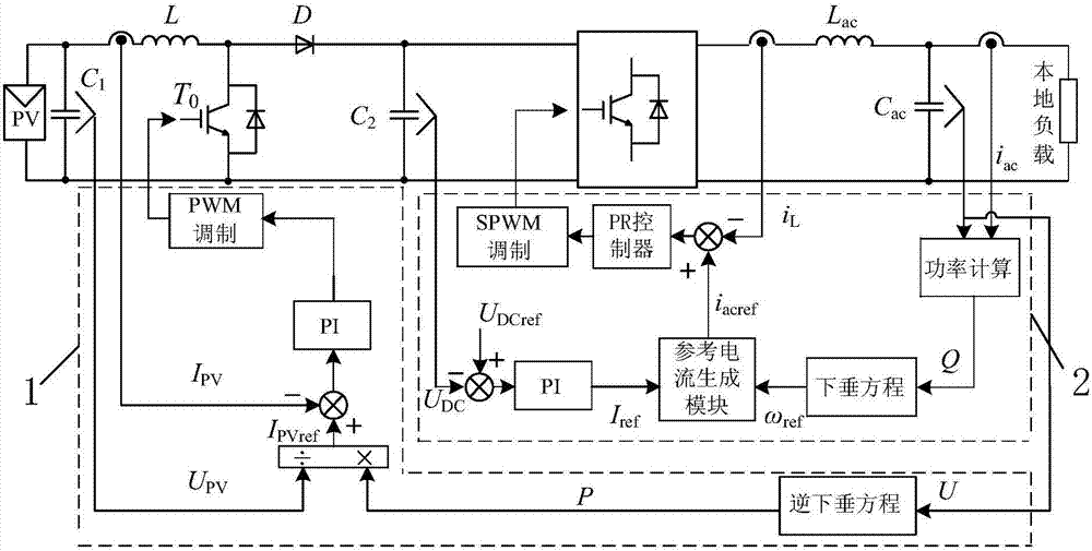
[0061] Specific implementation mode one: refer to figure 1 This embodiment is described in detail. In the off-grid control method of a photovoltaic microgrid system based on inverse droop control described in this embodiment, the photovoltaic microgrid system includes a capacitor C 1 , capacitance C ac , capacitance C 2 , diode D, full bridge inverter circuit VD, switch tube T 0 , inductance L and inductance Lac;

[0062] Capacitance C 1 Connect the two ends of the photovoltaic array PV to the output end of the capacitor C 1 One end of the inductor L is connected to one end of the inductor L, and the other end of the inductor L is connected to the switch tube T 0 The collector and the anode of the diode D, the switching tube T 0 The emitter, capacitor C 1 the other end of the capacitor C 2 One end of each is connected to an input end of the full-bridge inverter circuit VD, and the capacitor C 2 The other end of the diode D is connected to the negative pole of the diod...

specific Embodiment approach 2

[0070] Specific embodiment 2: This embodiment is to further explain the off-grid control method of photovoltaic microgrid system based on inverse droop control described in specific embodiment 1. In this embodiment, in step 1, the switching tube T 0 The specific process of driving the modulation signal is:

[0071] Using the inverse droop equation for capacitance C ac The voltage U at both ends is processed to obtain the reference power P output by the full-bridge inverter, and the reference power P output by the full-bridge inverter is divided by the capacitor C 1 Voltage at both ends U PV , get I PVref , and the photovoltaic array PV output current I PV After making a difference, perform PI adjustment to generate the switching tube T 0 drive modulation signal.

specific Embodiment approach 3

[0072] Specific embodiment three: This embodiment is a further description of the photovoltaic microgrid system off-grid control method based on inverse droop control described in specific embodiment one. In this embodiment, in step three, the off-grid inverter voltage output Module 2 pair U, i ac i L and I ref The specific process of processing and generating the driving signal of the full-bridge inverter is as follows:

[0073] Step 31, according to i ac and U to get the reactive power Q output by the full-bridge inverter circuit, use the droop equation to process the reactive power Q output by the full-bridge inverter circuit, and obtain the output reference angular frequency ω of the full-bridge inverter circuit ref ;

[0074] Step three two, I ref and ω ref Through the reference current generation module, generate the output current reference i of the full-bridge inverter circuit acref ;

[0075] Step three three, i acref with i L Perform PR control after making...


PUM


Abstract

A photovoltaic micro-network-system off-grid/grid-connected control method based on inverse droop control relates to the off-grid/grid-connected switching field. By using traditional droop control, an output current of an inverter can not be directly controlled; under a grid connected state, quality of electric energy injecting into a power grid is uncontrollable; and a grid connected current wave shape can not reach an ideal state. By using the method of the invention, the above problems are solved. Under the off-grid and grid-connected states, an uniform current type controller is adopted. An off-grid constant power output module is used for driving a switch tube T0 so that output power of a preceding-stage converter is equal to input power of a backward-stage inverter. An off-grid inversion voltage output module is used for driving a full-bridge inversion circuit so as to stabilize a direct current bus voltage and output a sine alternating current voltage. A grid-connected power maximization output module is used for driving the switch tube T0 so as to realize maximum power output of the inverter. A grid-connected current output module is used for driving the full-bridge inversion circuit so as to stabilize the direct current bus voltage and make an output current unit power factor be in a grid-connected state. The method is used for off-grid and grid-connected seamless switching of the inverter.

Description

technical field [0001] The invention relates to a control method for off-grid / grid-connection of a photovoltaic micro-grid system. It belongs to the field of off / grid switching. Background technique [0002] Photovoltaic microgrid has two working modes: grid-connected operation and off-grid operation. During grid-connected operation, the photovoltaic unit converts solar energy into electrical energy, and feeds excess electrical energy into the grid while supplying power to the electrical load. Off-grid operation means that the photovoltaic inverter is disconnected from the large power grid through a static switch, and all the energy of the photovoltaic unit is supplied to the local load to ensure the normal operation of the local power load. Corresponding to the two operating modes of the microgrid, it is necessary to design corresponding control strategies at the control level to achieve stable operation in the two operating states and switching transients. The tradition...

Claims


Application Information

Patent Timeline
Patent Type & Authority Applications(China)
IPC IPC(8): H02J3/38
CPCH02J3/383H02J3/388Y02E10/56
Inventor 刘鸿鹏张伟孙柏楠周佳杰王盼宝刘桂花王卫
Owner HARBIN INST OF TECH
Why Eureka
Try Eureka