
Flowerpot

A flower pot and pot body technology, which is applied in general water supply conservation, plant protection, drinking water installations, etc., can solve the problems of falling ash of flowers and leaves, affecting the appearance, poor air quality, etc., to increase air permeability and prevent strong light burns , the effect of maintaining the balance of water and air

Inactive Publication Date: 2017-10-20
傅明尧
View PDF0 Cites 1 Cited by
  • Summary
  • Abstract
  • Description
  • Claims
  • Application Information

AI Technical Summary

Problems solved by technology

However, modern people have a fast pace of life and high work pressure, so they often have no time to take care of flowers. At the same time, excessive industrialization and urbanization have led to poor air quality and severe smog in some areas, which makes the flowers and leaves fall seriously and affect the appearance.
At present, there are many new types of flower pots to achieve the purpose of automatic watering by improving the structure or adding intelligent systems, but these watering measures are not environmentally friendly

Method used


Image

  • Flowerpot
  • Flowerpot
  • Flowerpot

Examples


Embodiment 1

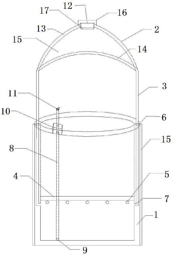
[0026] like figure 1 As shown, the present invention provides a novel flower pot, comprising a pot body (1), a rain-collecting shed (2) and a hollow column (3) connecting the pot body and the rain-collecting shed, and the inner chamber of the pot body (1) is provided with The horizontal clapboard (4) of leak hole is divided into upper flowerpot (44) and lower reservoir (45), and basin body (1) is provided with flood discharge hole (5) at reservoir side wall upper end, and reservoir ( 45) When the medium water is overloaded, it can be discharged from the flood discharge hole (5); the side wall of the basin body (1) is provided with a hollow column channel (6), and the column channel (6) passes through an adjustable column (3) The upper end of the inner wall of the pool (45) is provided with a water outlet (7); the basin body (1) is provided with a hollow water spray pipe (8), and the water spray pipe (8) is provided with a Water inlet (9), is provided with water spray controll...

Embodiment 2

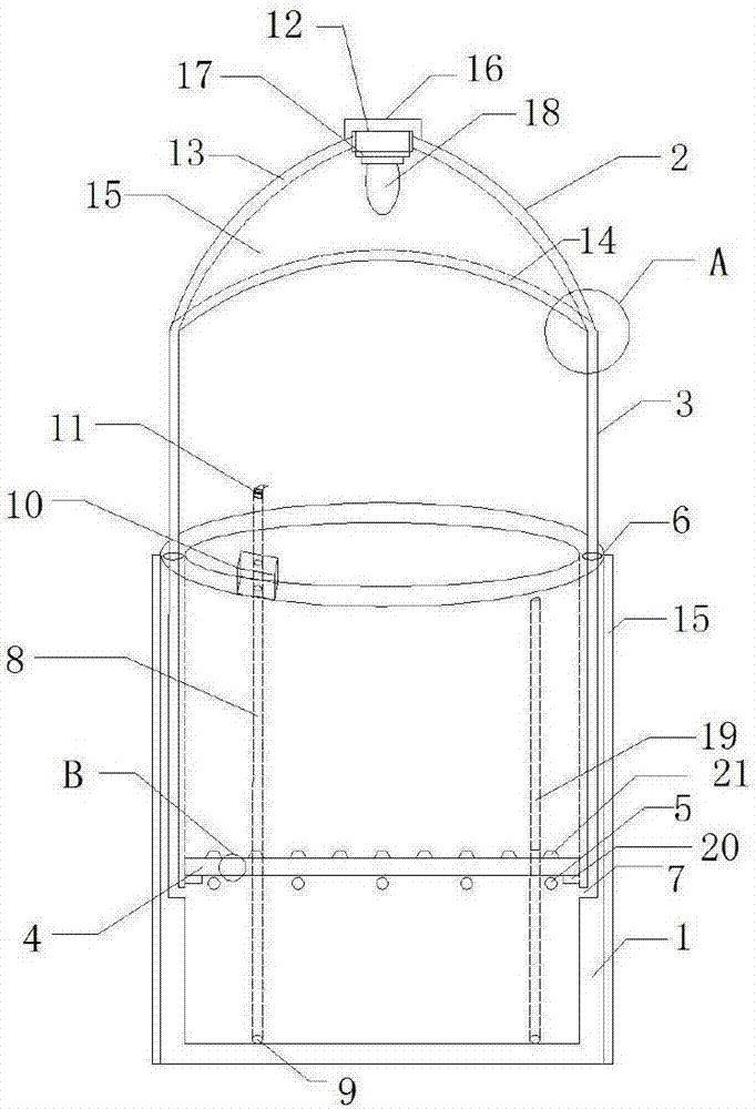
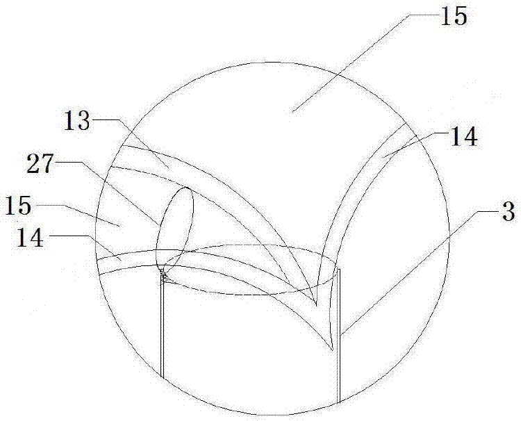
[0028] like figure 2 , image 3 and Figure 4 shown in figure 1 On the basis of the shown flowerpot, an illuminating lamp (18) is added, arranged under the accumulator (17) and connected to it; grid pipes (19), grid pipes (19), etc. are also added to the inner wall of the pot body (1) The distance arrangement extends from the lower part of the inner wall of the basin to the upper part, and the grid pipe (19) has a built-in water-conducting material; a supporting block (20) is also provided at the same height of the inner wall of the basin body (1), and a partition (20) is placed on the supporting block (20). 4), the clapboard (4) is made up of upper and lower two layers of metal mesh (41,43) shells and a layer of granular water-absorbing material (42) liner, and the metal mesh of the clapboard (4) is also provided with arc-shaped projections ( twenty one);

Embodiment 3

[0030] like Figure 5 shown in figure 1 On the basis of the shown flowerpot, an illuminating lamp (18) is added, arranged under the storage battery (17) and connected to it; a bracket (20) is also set at the same height of the inner wall of the pot body (1), and on the bracket (20) Place the partition (4), the partition (4) is composed of upper and lower layers of metal mesh (41, 43) shells and a layer of granular water-absorbing material (42) liner, the metal mesh of the partition (4) is also provided with circular arcs shaped protrusion (21); the upper basin body of the dividing plate (4) has an inner basin (24) with a hole; the central part of the dividing plate (4) is provided with a columnar dome bump (25), and the inner basin (24) The outer bottom surface is recessed inwardly to form a concave hole (26) corresponding to the bump (25), and the bump (25) is rotatably connected to the concave hole (26) of the inner basin; the top of the column (3) is provided with a veneti...


PUM


Abstract

The invention provides a flowerpot. The flowerpot comprises a pot body, a rainwater collecting canopy and a hollow upright column, wherein the pot body is divided into an upper flower pot and a lower water reservoir by a partition plate, flood discharge holes are formed in the upper end of the side wall of the water reservoir, a hollow upright column passage and a water spraying pipeline are arranged inside the side wall of the pot body, the upright column penetrates into the upright column passage, and a water outlet is formed in the upper end of the internal sidewall of the water reservoir; the water spraying pipeline is provided with a water inlet at the lower end of the internal sidewall of the water reservoir and a water spraying controller at a pot opening, and the water spraying controller is provided with a spraying nozzle; the rainwater collecting canopy consists of a center ring and equidistant arc-shaped beam columns which are integrated with the circumferential direction of the center ring, an arc-shaped water guiding chute is formed between free ends of every two adjacent beam columns, and the free ends of the beam columns are converged with the water guiding chutes, extend to a hollow part of the upright column and are fixed; thin-film solar cells, of which edges extend into the water guiding chutes, are arranged on the external sidewall of the pot body and the beam columns; and a rainproof top cover is arranged on the center ring, and a storage battery connected with the water spraying controller and the thin-film solar cells is arranged below the rainproof top cover. The flowerpot provided by the invention integrates automatic watering, lighting supplementing, dust prevention and removal and visual attractiveness.

Description

technical field [0001] The invention relates to a tool in the field of daily necessities, in particular to a flowerpot. Background technique [0002] At present, the improvement of living standards makes growing flowers an important way for people to relax. Flowers can not only provide a pleasing experience for the senses, but also purify the air and absorb radiation to give people health in essence. However, modern people have a fast pace of life and high work pressure, so they often have no time to take care of flowers. At the same time, excessive industrialization and urbanization have led to poor air quality, and severe smog in some areas, which makes flowers and leaves fall seriously and affects the appearance. At present, many new flower pots realize the purpose of automatic flower watering by improving the structure or adding an intelligent system, but these flower watering measures are not environmentally friendly enough. Contents of the invention [0003] The in...

Claims


Application Information

Patent Timeline
Patent Type & Authority Applications(China)
IPC IPC(8): A01G9/02A01G9/26A01G13/02A01G27/00E03B3/03
CPCA01G9/02A01G9/26A01G13/0212A01G27/00E03B3/03Y02A20/00Y02A20/108Y02A40/25
Inventor 傅明尧
Owner 傅明尧
Learn More