Wrench
A wrench and shaft technology, applied in the field of wrenches, can solve the problems of narrow use range, labor-intensive, unable to cover bolt removal work, etc., and achieve the effect of improving practicability and small size
- Summary
- Abstract
- Description
- Claims
- Application Information
AI Technical Summary
Problems solved by technology
Method used
Image
Examples
Embodiment 1
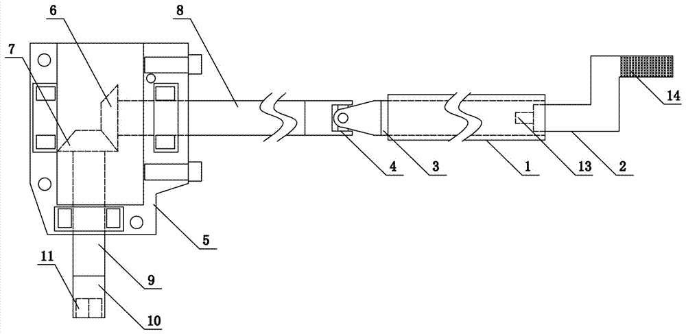
[0031] like figure 1 As shown, the present invention includes a first connecting rod 1, a steering mechanism and an operating handle 2. The outer wall of the operating handle is provided with X-shaped anti-slip lines 14. The first connecting rod 1 is a hollow tube and is rotatably connected to the first rotating shaft 3. The operating handle 2 is plugged with the right end of the first rotating shaft 3, and the specific implementation method can be matched with the plug-in block 13 and the socket that cooperate with each other. The left end of the first rotating shaft 3 extends out of the first connecting rod 1 and is fixedly installed with the universal joint 4. The universal joint 4 adopts a cross-shaft rigid universal joint. The steering mechanism includes a housing 5 and a first bevel gear 6 and a second bevel gear 7 arranged in the housing 5. The first bevel gear 6 coaxially fixes the second rotating shaft 8. The right end of the second rotating shaft 8 extends out of the...
Embodiment 2
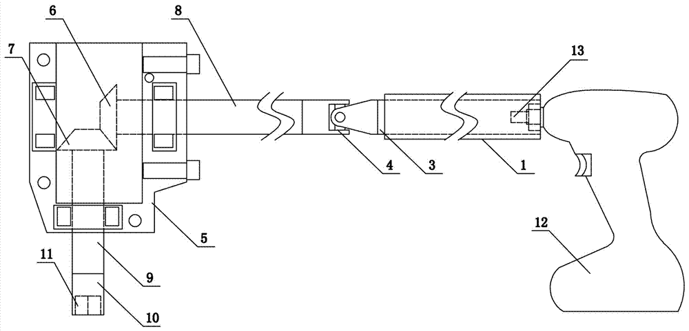
[0034] like figure 2 As shown, the present invention includes a first connecting rod 1, a steering mechanism and a motor 12. The motor 12 adopts a hand-held motor with a forward and reverse switch in the prior art that can rotate in both forward and reverse directions. The first connecting rod 1 is a hollow tube and its The first rotating shaft 3 is connected by internal rotation, and the operating handle 2 is inserted into the right end of the first rotating shaft 3. The specific implementation method can be matched with the plug-in block 13 and the jack, and the left end of the first rotating shaft 3 protrudes from the first connecting rod. 1. The universal joint 4 is installed externally and fixedly. The universal joint 4 adopts a cross-shaft rigid universal joint. The steering mechanism includes a casing 5 and a first bevel gear 6 and a second bevel gear 7 arranged in the casing 5. The first bevel The gear 6 coaxially fixes the second rotating shaft 8, and the right end o...
Embodiment 3
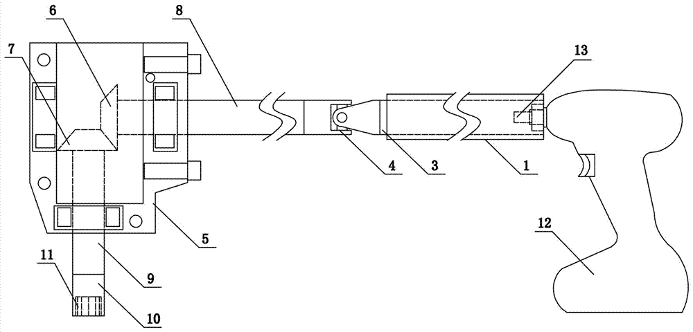
[0037] like image 3 As shown, the present invention includes a first connecting rod 1, a steering mechanism and a motor 12. The motor 12 adopts a hand-held motor with a forward and reverse switch in the prior art that can rotate in both forward and reverse directions. The first connecting rod 1 is a hollow tube and its The first rotating shaft 3 is connected by internal rotation, and the operating handle 2 is inserted into the right end of the first rotating shaft 3. The specific implementation method can be matched with the plug-in block 13 and the jack, and the left end of the first rotating shaft 3 protrudes from the first connecting rod. 1. The universal joint 4 is installed externally and fixedly. The universal joint 4 adopts a cross-shaft rigid universal joint. The steering mechanism includes a casing 5 and a first bevel gear 6 and a second bevel gear 7 arranged in the casing 5. The first bevel The gear 6 coaxially fixes the second rotating shaft 8, and the right end of...
PUM
 Abstract
Description
Claims
Application Information
 - R&D
- Intellectual Property
- Life Sciences
- Materials
- Tech Scout
- Unparalleled Data Quality
- Higher Quality Content
- 60% Fewer Hallucinations
Browse by: Latest US Patents, China's latest patents, Technical Efficacy Thesaurus, Application Domain, Technology Topic, Popular Technical Reports.
© 2025 PatSnap. All rights reserved.Legal|Privacy policy|Modern Slavery Act Transparency Statement|Sitemap|About US| Contact US: help@patsnap.com


