Electromagnetic positioning vibration isolation platform

A vibration isolation platform and electromagnetic positioning technology, which is applied to aerospace equipment, aerospace vehicles, aircraft, etc., can solve the problems of inability to measure and control micro-vibration acceleration, and complex installation of measuring components.

Active Publication Date: 2017-10-20
ZHEJIANG UNIV
View PDF6 Cites 7 Cited by
  • Summary
  • Abstract
  • Description
  • Claims
  • Application Information

AI Technical Summary

Problems solved by technology

[0003] In order to overcome the disadvantages of complicated installation of position measuring components in the prior art and the inability to effectively measure and control micro-vibration accelerations, the present invention proposes an electromagnetic positioning and vibration-isolation platform that is simple to install and arrange components and can measure and control micro-accelerations

Method used


Image

  • Electromagnetic positioning vibration isolation platform
  • Electromagnetic positioning vibration isolation platform
  • Electromagnetic positioning vibration isolation platform

Examples


Embodiment 1

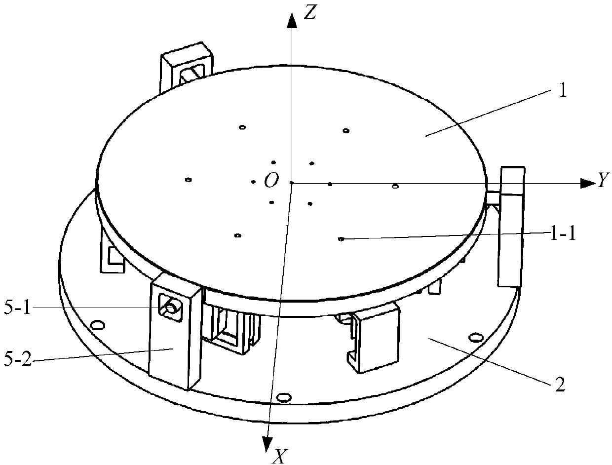
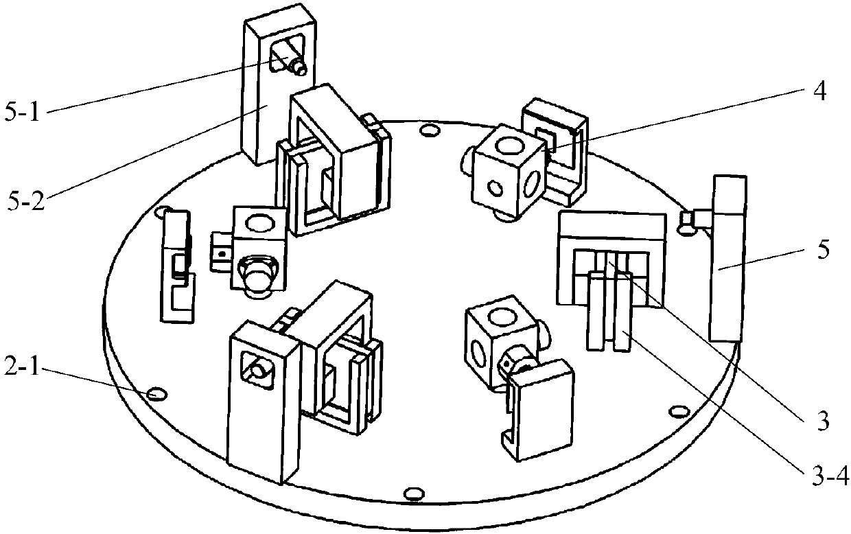
[0034] Such as figure 1 and 2 The electromagnetic positioning vibration isolation platform shown has a base 2, a working platform 1, a force output system, an acceleration measurement unit, a position measurement unit and a controller; the force output system is composed of 3 sets of two-axis electromagnetic exciters, The two-axis electromagnetic exciter connects the working platform 1 and the base 2 without contact through the Lorentz force, and the two-axis electromagnetic exciter is arranged in a uniform array along the same circle at 120° with the center of the working platform 1 as the center; the acceleration measurement unit consists of 6 The linear acceleration sensor 4-2 is formed, and every two linear acceleration sensors are installed orthogonally on an acceleration sensor installation block 4-1, and the acceleration sensor installation block 4-1 is fixed with the working platform 1, and the center of the working platform 1 is the center of the circle along the Th...

Embodiment 2

[0050] The difference between this embodiment and Embodiment 1 lies in that the coils are wound in different ways. The rest of the structure is the same as that of Embodiment 1 except for the coil.

[0051] The specific structure of the coil is as follows: Figure 3-2 -1 and 3-2-2, the coil contains x to the coil set 112 and z To the coil set 122, x to the coil set 112 and z The directional coil group 122 is formed by respective first sub-coils and second sub-coils, the first sub-coils and the second sub-coils are adjacent and wound by a wire, the first sub-coils are wound counterclockwise from inside to outside, and the second sub-coils are wound from inside to outside. The second sub-coil is wound clockwise from the outside to the inside, the first sub-coil and the second sub-coil are in the same plane, the first sub-coil and the second sub-coil are respectively wound with multiple turns, and each turn is composed of an effective wire segment and a connecting wire segme...

Embodiment 3

[0054] The difference between this embodiment and Embodiment 1 lies in that the coils are wound in different ways. The rest of the structure is the same as that of Embodiment 1 except for the coil.

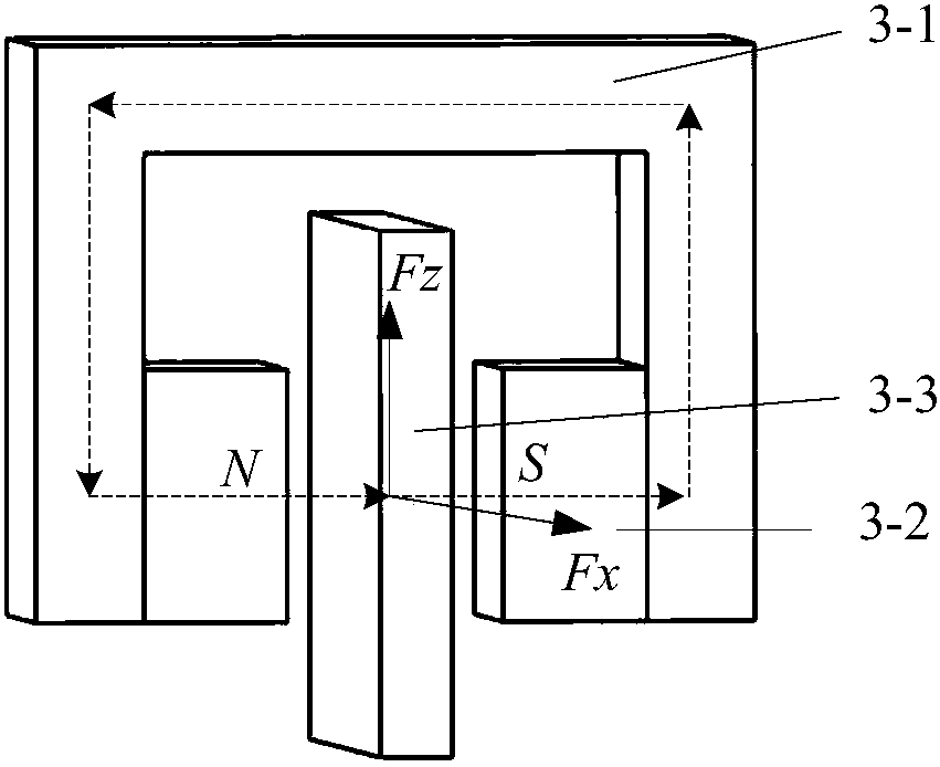
[0055] The specific structure of the coil is as follows: Figure 3-3 shown, the coil contains x to coil 123 and z to the coil 113, x In the coil 123, the multi-turn wire segments that are located in the working magnetic field shown by the dotted line box are equidistantly distributed to form z To the Lorentz force generation department, x The wire segment located outside the working magnetic field to the coil 123 is used as the connecting wire segment; z To the equidistant distribution of multi-turn wire segments in the magnetic field in the coil 113 is formed x To the Lorentz force generation department, z The conductor segments lying outside the magnetic field to the coil 113 serve as connecting conductor segments. to produce perpendicular x Lorentz force sum z to the ...


PUM


Abstract

An electromagnetic positioning vibration isolation platform comprises a base, a working platform, an acting force output system, an acceleration measuring unit, a position measuring unit and a controller; three groups of biaxial electromagnetic exciters form the acting force output system; the biaxial electromagnetic exciters consist of first working parts and second working parts; the first working parts comprise permanent magnets and magnet yokes; the permanent magnets and the magnet yokes form closed magnetic circuits; the magnet yokes are fixed together with a working platform; the second working parts comprise circuit boards and coil brackets; the coil brackets are fixed together with the base; the circuit boards are fixed on the coil brackets; coils are arranged on the circuit boards; the coils are positioned within the closed magnetic circuits; all magnetic force lines that penetrate through the coils have same directions; the coils comprise (i)x(/i)-direction lorentz force generation parts and (i)z(/i)-direction lorentz force generation parts; current directions of all leads in the (i)x(/i)-direction lorentz force generation parts are as same as each other; and current directions of all leads in the (i)z(/i)-direction lorentz force generation parts are as same as each other. The electromagnetic positioning vibration isolation platform has the advantages that each component is simply mounted and placed and the micro acceleration speed can be measured and controlled.

Description

technical field [0001] The invention relates to an electromagnetic positioning and vibration-isolation platform serving sensitive airborne equipment of spacecraft. technical background [0002] With the continuous development of the aerospace industry, there are more and more stringent requirements for the positioning accuracy and stability of spacecraft airborne sensitive equipment. These airborne sensitive equipment include space telescopes, reconnaissance cameras, space interferometers and Life science experimental devices, fluid experimental devices, etc. in space laboratories. Since the above-mentioned sensitive equipment is in orbit, it will be affected by the disturbance introduced by the operation of the equipment itself, the operation of other equipment on the spacecraft, and the activities of the astronauts, so that the spacecraft cannot provide the sensitive equipment with the required positioning accuracy and microgravity conditions. , so it is very meaningful t...

Claims


Application Information

Patent Timeline
Patent Type & Authority Applications(China)
IPC IPC(8): B64G1/66
CPCB64G1/66
Inventor 何闻李劲林贾叔仕
Owner ZHEJIANG UNIV
Why Eureka
Try Eureka