Semi-automatic torque coupling device

A coupling device and semi-automatic technology, applied in the direction of elastic coupling, directional drilling, mechanical equipment, etc., can solve the problems of affecting drilling efficiency, large frictional resistance drill bit, depressurization, etc.

Pending Publication Date: 2017-10-20
中石化石油工程技术服务有限公司 +2
View PDF8 Cites 2 Cited by
  • Summary
  • Abstract
  • Description
  • Claims
  • Application Information

AI Technical Summary

Problems solved by technology

The steady-deviation well section is mainly compound drilling, that is, the drilling tool assembly rotates as a whole. At this time, the friction pair between the drill string and the well wall is rolling friction, and the frictional resistance is small, which is conducive to rapid drilling; In China, a sliding drilling system powered by a mud motor is mainly used to carry out drilling operations. The power drilling tool drives the drill bit to rotate and break rocks. The drill string itself does not rotate, but lies flat on the bottom of the well due to its own weight. The friction pair between them belongs to sliding friction, which leads to high friction resistance and makes it difficult to effectively apply WOB to the drill bit, resulting in "pressure-off" phenomenon, which affects drilling efficiency
Because of the rotary steerable drilling technology in foreign countries, it has been able to completely overcome the friction problem during steerable drilling. The research on rotary steerable drilling technology is actively carried out in China. However, due to the technical monopoly of foreign countries and the limitations of key components, there has been no successful industrial application at present. Relying only on imports or renting products from foreign companies greatly increases the comprehensive cost of drilling

Method used


Image

  • Semi-automatic torque coupling device
  • Semi-automatic torque coupling device
  • Semi-automatic torque coupling device

Examples


Embodiment Construction

[0019] The present invention will be described in detail below in conjunction with the accompanying drawings.

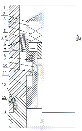
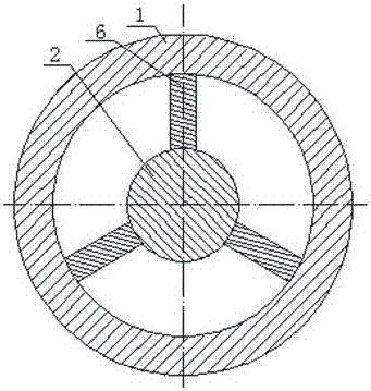
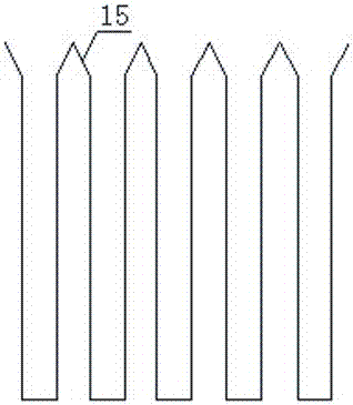
[0020] Refer to attached figure 1 , figure 2 and image 3 , the semi-automatic torque coupling device is mainly composed of upper housing 1, protective device 2, pressure transmission hole 3, pressure sensing device 4, stepping motor 5, fixed rib 6, transmission shaft 7, sealing device 8, bypass hole 9, The spline shaft 11, the bearing 12, the lower casing 14, and the spline introduction body 15 are composed. The protective device 2 is fixed inside the upper casing 1, the pressure sensing device 4 and the stepping motor 5 are installed inside the protecting device 2, the pressure sensing device is installed on the upper end of the stepping motor 5, and the transmission shaft 7 is installed on the stepping motor 5 The lower end of the protective device 2 and the upper shell 1 is installed with a fixed rib plate 6, the upper part of the protective device 2 is proce...


PUM


Abstract

The invention relates to a semi-automatic torque coupling device in the field of a petroleum and gas well drilling device. The device is mainly composed of an upper shell, a protection device, a pressure transfer hole, a pressure sensing device, a stepping motor, a fixed rib plate, a transmission shaft, a seal device, a bypass hole, a spline shaft, a bearing, a lower shell and a spline leading-in body. In the drilling process, torque generated by a ground device is transmitted to a well bottom drill bit along a drill combination, the semi-automatic torque coupling device is mounted in the drill combination according to drill well design, an operator uses opening and closing of a motor in a drilling fluid remote control part so as to control the spline shaft to stretch out of or retract and be locked, torque connection and disconnection are achieved, the semi-automatic torque coupling device can effectively solve the pressure dragging problem commonly existing in the drilling process of complex structure wells of long horizontal segment horizontal wells, large displacement wells and the like, and the device has the important significance in further reducing sliding friction resistance between the drill combination and the well wall, improving the well hole smoothness and improving the drilling efficiency of the complex structure wells.

Description

technical field [0001] The invention relates to the fields of oil and gas drilling, coal bed gas drilling, geological exploration and mine drilling devices, in particular to a semi-automatic torque coupling device. Background technique [0002] During the drilling process of complex structure wells such as directional wells, long horizontal section horizontal wells, high-inclination wells, and extended-reach wells, the torque generated by ground equipment is transmitted along the drill string to the bottom hole bit, driving the bit to rotate and break rock. Drilling is mainly completed by the combination of sliding drilling and compound drilling. The steady-deviation well section is mainly compound drilling, that is, the drilling tool assembly rotates as a whole. At this time, the friction pair between the drill string and the well wall is rolling friction, and the frictional resistance is small, which is conducive to rapid drilling; In China, a sliding drilling system powe...

Claims


Application Information

Patent Timeline
Patent Type & Authority Applications(China)
IPC IPC(8): F16D3/06E21B7/04
CPCE21B7/04F16D3/06
Inventor 李文飞周延军李玄烨夏文安陈合晶刘新华胡高群于丽丽梁凤杰盖微
Owner 中石化石油工程技术服务有限公司
Why Eureka
Try Eureka