Measuring method based on dispersion optical fiber dispersion coefficient measuring system

A dispersion coefficient and measurement system technology, which is applied in the direction of measuring devices, optical instrument testing, machine/structural component testing, etc., can solve problems such as slow measurement speed, low measurement accuracy, and poor anti-environmental interference performance, so as to reduce the impact, The effect of improving accuracy

Active Publication Date: 2017-10-20
西安华兴搏发光电科技股份有限公司
View PDF4 Cites 17 Cited by
  • Summary
  • Abstract
  • Description
  • Claims
  • Application Information

AI Technical Summary

Problems solved by technology

[0004] The technical problem to be solved by the present invention is that the existing measurement system has slow measurement speed, low measurement accuracy, and poor anti-environmental interference performance. A new measurement system for dispersion coefficient of dispersion fiber is provided

Method used


Image

  • Measuring method based on dispersion optical fiber dispersion coefficient measuring system
  • Measuring method based on dispersion optical fiber dispersion coefficient measuring system
  • Measuring method based on dispersion optical fiber dispersion coefficient measuring system

Examples


Embodiment Construction

[0037] The present invention will be further explained below in conjunction with the accompanying drawings and specific embodiments. It should be understood that the following specific embodiments are only used to illustrate the present invention and are not intended to limit the scope of the present invention.

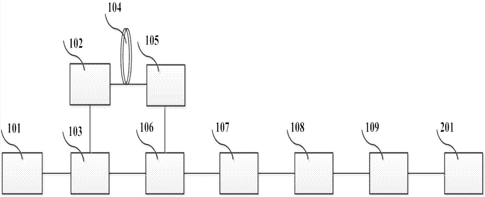
[0038] As shown in the figure, a system for measuring the dispersion coefficient of a dispersion fiber includes a signal source 101, a directly modulated laser 102, a power divider 103, a dispersion fiber to be measured 104, a high-speed photodetector 105, an IQ mixer 106, and a low-pass filter device 107, signal amplifier circuit 108, data acquisition circuit 109, signal processing and display module 201, the high-frequency microwave signal output by the signal source 101 is divided into two microwave signals after the power divider 103, and the power divider 103 The microwave signal of one path enters the direct modulation laser 102, and the laser loads the microwave...


PUM


Abstract

The invention relates to a measuring method based on a dispersion optical fiber dispersion coefficient measuring system, mainly in order to solve the problem that the existing measuring system has the disadvantages of low measuring speed, low measuring accuracy and poor anti-environmental-interference performance. A dispersion optical fiber dispersion coefficient measuring system includes a signal source. A high-frequency microwave signal output by the signal source is divided into two microwave signals after passing through a power divider. One microwave signal of the power divider enters a directly modulated laser. The laser loads the microwave signal to the optical domain to get an optical microwave signal. The optical microwave signal passes through a dispersion optical fiber to be measured, is incident on a high-speed photoelectric detector, and then enters the radio frequency input end of an IQ frequency mixer. The other microwave signal of the power divider enters the local oscillation input end of the IQ frequency mixer, passes through a low-pass filter, and then sequentially passes through a signal amplification circuit, a data acquisition circuit and a signal processing and display module. Through the technical scheme, the problem is well solved. The measuring method can be used to measure a dispersion optical fiber.

Description

technical field [0001] The invention relates to a measurement method based on a dispersion coefficient measurement system of a dispersion fiber. Background technique [0002] Optical fiber dispersion coefficient is one of the key parameters of optical fiber, and its measurement method is also an important research direction of optical fiber parameter measurement technology. The dispersion coefficient of the dispersion fiber directly determines the dispersion compensation characteristics and nonlinear characteristics of the dispersion fiber, and is one of the most important parameters of the dispersion fiber. Traditional measurement methods are realized by pulse delay method, phase shift method, mode field diameter method and white light interference. Sophisticated time-frequency analysis algorithms to calculate and analyze measurement results. [0003] Another example is the Chinese patent document CN 205538163 U, which discloses a fiber optic dispersion coefficient measur...

Claims


Application Information

Patent Timeline
Patent Type & Authority Applications(China)
IPC IPC(8): G01M11/02
CPCG01M11/0285
Inventor 卢平
Owner 西安华兴搏发光电科技股份有限公司
Why Eureka
Try Eureka