Optical Reflection Film, Manufacturing Method Thereof, Optical Control Film Using Optical Reflection Film, Optical Film, Functional Glass And Head-up Display
A technology of light reflective film and light control film, which is applied in optics, optical components, instruments, etc., can solve the problems of legal restrictions, difficult application and high reflectivity, etc., and achieve the effect of improving visibility and easy processing of laminated glass
- Summary
- Abstract
- Description
- Claims
- Application Information
AI Technical Summary
Problems solved by technology
Method used
Image
Examples
Embodiment 1
[0119]
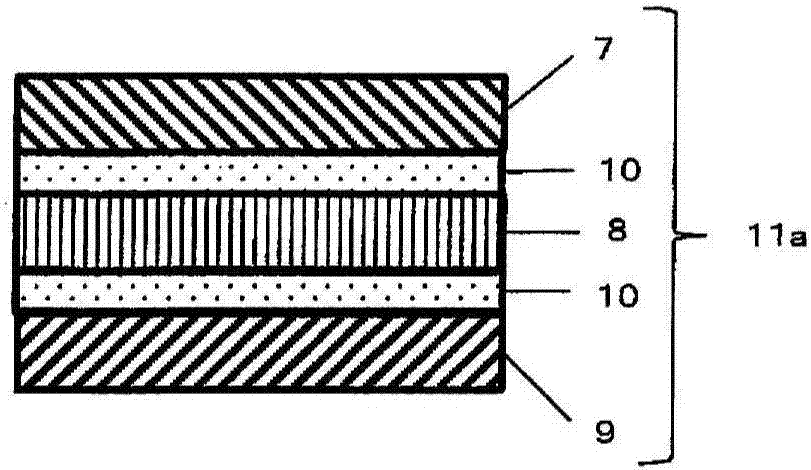
[0120] Using the prepared coating solutions (R1), (R2), (R3), the light reflective layer PRL-1, the light reflective layer PRL-2, and the light reflective layer PRL-3 were prepared according to the following steps, and then they were laminated And the light reflection film of this invention was produced. As the plastic substrate, a PET film manufactured by Toyobo Co., Ltd. (trade name A4100, thickness), which was previously rubbed on the surface of the primerless coating layer by the method described in Example 1 of JP 2002-90743 A, was used. 50μm) long rolls. The spectroscopic characteristics shown below were evaluated by measuring the reflection spectrum with a spectrophotometer MPC-3100 manufactured by Shimadzu Corporation.
[0121] (1) Using a gravure contact reverse coater (manufactured by Yasui Seiki Co., Ltd.), each coating solution was applied to the rubbing treatment surface of each PET film at room temperature, so that each light obtained after drying was refl...
Embodiment 2
[0141] The light reflection layer PRL-4 (using the coating liquid (R4)) was obtained on the PET film by the same production method as in Example 1 except for using the coating liquid (R4). The PET film on the light reflective layer PRL-3 side of the light reflective film obtained from (1) to (5) of Example 1 was peeled off, and then the light reflective layer PRL-4 on the PET film was removed using an acrylic adhesive. The light reflection layer side and the light reflection layer side of the light reflection layer PRL-3 from which the PET film has been peeled are laminated on each other, thereby obtaining a planar shape with PET films on both outer sides and further laminated with the light reflection layer PRL-4 The laminated film. Next, about 10 m of the laminated film was wound on a 76.2 mm (3 inch) plastic core, and placed in a 35° C. thermostat in a roll state for 48 hours. After unwinding the laminated film from the roll and cutting it into 15 cm squares, the PET films ...
Embodiment 3
[0145] The PET film of the light reflection layer PRL-4 of the flat-shaped laminate film further laminated with the light reflection layer PRL-4 obtained in Example 2 was peeled off, and the light reflection layer PRL-4 was peeled off the light of the PET film On the reflective layer side, a wide-band quarter wave plate (manufactured by Teijin Co., Ltd.: PUREACE WR-S), which is a light control layer, was bonded with an adhesive to produce a flat light control film. Next, about 10 m of the film was wound on a 76.2 mm (3 inch) plastic core, and it was placed in a thermostat at 80° C. for 3 hours in a roll state. After unwinding the laminated film from the roll and cutting into 15 cm squares, the PET films located on both outer sides of the laminated light reflection layer PRL-1 were peeled off. In this way, the curved light control film of the present invention in which the light reflection layer PRL-1 to the light reflection layer PRL-4 and the quarter wave plate as the light co...
PUM
| Property | Measurement | Unit |
|---|---|---|
| Thickness | aaaaa | aaaaa |
| Radius of curvature | aaaaa | aaaaa |
| Half width | aaaaa | aaaaa |
Abstract
Description
Claims
Application Information
 - R&D
- Intellectual Property
- Life Sciences
- Materials
- Tech Scout
- Unparalleled Data Quality
- Higher Quality Content
- 60% Fewer Hallucinations
Browse by: Latest US Patents, China's latest patents, Technical Efficacy Thesaurus, Application Domain, Technology Topic, Popular Technical Reports.
© 2025 PatSnap. All rights reserved.Legal|Privacy policy|Modern Slavery Act Transparency Statement|Sitemap|About US| Contact US: help@patsnap.com


