Video monitoring system fault self-detection and self-recovery control system and method

A video surveillance system and fault self-checking technology, applied in CCTV systems, electrical testing/monitoring, etc., can solve problems such as noise interference, camera interference, and difficulty in judging fault points, so as to reduce safety costs, save manpower, and reduce inspections The effect of workload and difficulty

Active Publication Date: 2017-10-20
武汉瑞科兴业科技有限公司
View PDF15 Cites 23 Cited by
  • Summary
  • Abstract
  • Description
  • Claims
  • Application Information

AI Technical Summary

Problems solved by technology

Second, camera interference, it is often due to human factors that cause the video surveillance screen to deviate from the normal screen, such as video signal interruption or camera occlusion, etc.
However, in practical applications, standard reference images are difficult to provide
The main reasons are as follows: 1) It is difficult to extract a clean background image
Because background modeling and other methods are difficult to obtain a clean background image, there will be certain noise interference; 2) Extracting the background image consumes a lot of computing resources
[0005] The conventional video surveillance control box is a carrier of field equipment, which mainly plays the functions of field equipment placement, power distribution, field equipment signal access, maintenance, etc.; usually monitors and controls according to the distribution of the number of cameras on the scene and the working conditions of the scene The layout and installation of the box, the control box has a built-in plug-in strip, switching power supply, switch, optical conversion equipment, etc., the camera signal and power supply are connected to the corresponding equipment in the box, and are connected to the master control center through the access switch and optical cable; but when If the system is large, there are many camera points, the installation is scattered, and the installation area is wide, there will be problems such as equipment operation, fault status cannot be monitored, maintenance and addressing work is large, and fault points are difficult to judge.

Method used


Image

  • Video monitoring system fault self-detection and self-recovery control system and method
  • Video monitoring system fault self-detection and self-recovery control system and method
  • Video monitoring system fault self-detection and self-recovery control system and method

Examples


Embodiment Construction

[0036] The following will clearly and completely describe the technical solutions in the embodiments of the present invention with reference to the accompanying drawings in the embodiments of the present invention. Obviously, the described embodiments are only some, not all, embodiments of the present invention. Based on the embodiments of the present invention, all other embodiments obtained by persons of ordinary skill in the art without creative efforts fall within the protection scope of the present invention.

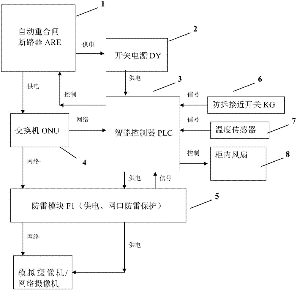
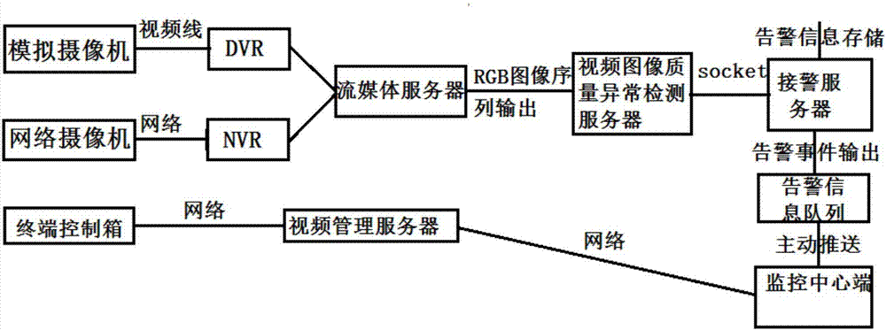
[0037] like figure 2 , Embodiment 1, a video monitoring system fault self-diagnosis self-recovery control system, including: the equipment layer is composed of a terminal control box, DVR, NVR, network camera, analog camera, and matrix. Analog cameras and network cameras acquire video streams, the matrix is ​​used to control and manage video streams, and the terminal control box is used for fault self-checking of network cameras and analog cameras;

[0038] The a...


PUM


Abstract

The invention discloses a video monitoring system fault self-detection and self-recovery control system and a method. The system includes a device layer, an access layer, a service layer, an interface layer, and a business layer. The device layer is composed of a terminal control box, a DVR, an NVR, a network camera, an analog camera, and a matrix. The access layer implements video stream access and video stream data interaction of the device layer based on a C+ + program. The service layer is used for processing and analyzing video data streams and storing and forwarding the detection result. The business layer is used for viewing alarm information. The problem that the conventional video monitoring device cannot monitor the operation or fault state of devices, bears high maintaining and addressing workload, and can hardly judge a fault is solved. The operation or fault state of each device in the whole system can be displayed, recorded and prompted in real time. Safe and stable operation of the system is ensured, the state can be monitored, and a fault point can be judged. The workload and difficulty of system device maintenance are reduced.

Description

technical field [0001] The invention relates to the fields of video monitoring and PLC automatic control. Background technique [0002] The security industry has grown into an emerging industry in the national economic industry with a large market size, a complete range of products, a wide range of application fields, and a high level of technology, and has become an important part of the social public security system. As an important component of the front-end camera, the video surveillance front-end control box also needs to be safe, reliable, and intelligent, and its important value is self-evident. It is widely used in video surveillance systems such as safe cities, security private network systems, intelligent transportation systems (ITS), highway video surveillance systems, video surveillance communities, factories, schools and other outdoor environments. [0003] Due to the abnormal quality of the video collected by the security equipment for a long time, we divide i...

Claims


Application Information

Patent Timeline
Patent Type & Authority Applications(China)
IPC IPC(8): G05B23/02H04N7/18
Inventor 姚龙腾叶亮
Owner 武汉瑞科兴业科技有限公司
Why Eureka
Try Eureka