Torque-current neural network switch reluctance machine control method and system

A technology of switched reluctance motor and neural network, which is applied in control system, torque ripple control, AC motor control, etc., and can solve problems such as difficult SRM torque effective control

Active Publication Date: 2017-10-20
GUILIN UNIV OF ELECTRONIC TECH
View PDF4 Cites 22 Cited by
  • Summary
  • Abstract
  • Description
  • Claims
  • Application Information

AI Technical Summary

Problems solved by technology

[0005] In the existing literature reports, in SRM modeling and control, the neural network used is a general neural network model, and the neural

Method used


Image

  • Torque-current neural network switch reluctance machine control method and system
  • Torque-current neural network switch reluctance machine control method and system
  • Torque-current neural network switch reluctance machine control method and system

Examples


Embodiment Construction

[0060] Embodiment of Torque-Current Neural Network Switched Reluctance Motor Control Method

[0061] The embodiment of the torque-current neural network switched reluctance motor control method includes the following steps:

[0062] Step I SRM torque distribution for each phase

[0063] In this example, the torque distribution function TSF adopts the optimal distribution function cubic distribution function, and its expression is:

[0064]

[0065] where f(θ) represents the cubic distribution function;

[0066] According to formula (1), the given total torque Distributed as the reference torque T of each phase kk , the torque distribution formula is as follows:

[0067]

[0068] In the formula To set the reference torque; T kk (θ) is the phase reference torque that changes with θ; f(θ) represents the cubic distribution function; θ is the rotor position angle; θ on is the opening angle; θ ov is the commutation overlap angle; θ off is the cut-off angle; kk=1,2,3...


PUM


Abstract

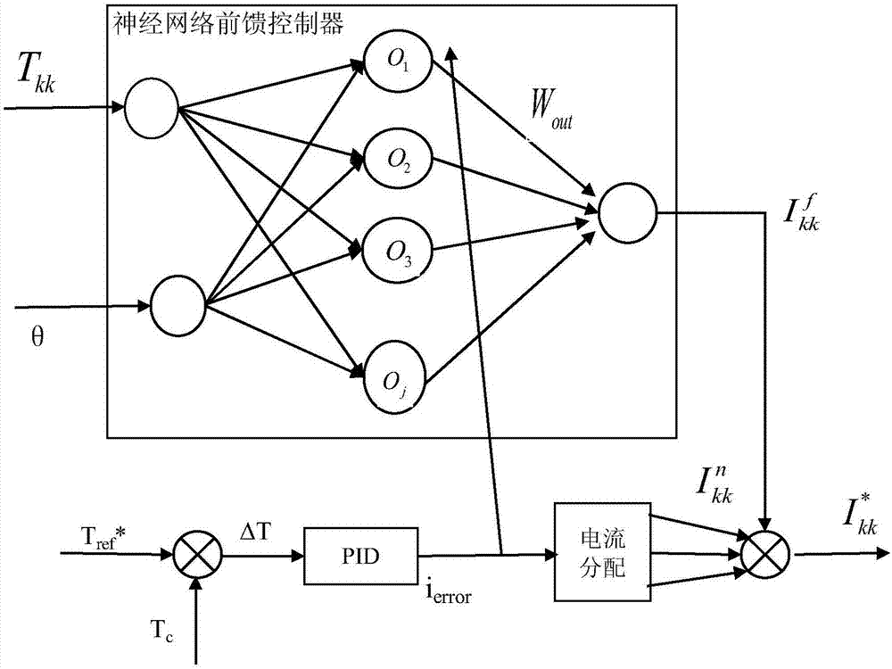
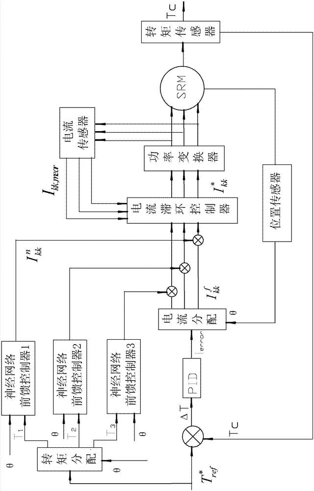
The invention discloses a torque-current neural network switch reluctance machine control method and system, and the method comprises the steps: configuring one neural network feedforward controller for each phase of an SRM, taking a torque-current inverse model as an activation function, taking the reference torque, distributed through given total torque, of each phase and the rotor position angle as the input, and achieving the feedback error learning through the output of a PID controller. The output of the neural network feedforward controller and the output of the PID controller are superposed to serve as a reference current which is transmitted to a current hysteresis loop controller, so as to control the operation of the SRM through combining with a current feedback signal at a current moment. The system SRM is provided with the current, position and torque sensors, and a signal processor comprises three neural network feedforward controllers, a torque distribution module, a PID control module and a current hysteresis loop control module. An inner loop current hysteresis loop controller tracks a reference current, and controls the operation of the SRM. The method gives full consideration to the special high nonlinearity of the SRM, and effectively reduces the torque pulsation of the SRM.

Description

technical field [0001] The invention relates to the technical field of control of switched reluctance motors for driving new energy vehicles, in particular to a torque-current neural network switched reluctance motor control method and system. Background technique [0002] At present, energy and environmental issues are becoming more and more prominent, and electric vehicles have received extensive attention and have great development prospects. Compared with other motors, SRM (Switched Reluctance Motor, SRM in this article means switched reluctance motor) has many excellent characteristics such as simple and strong structure, no need for rare earth materials, and is suitable for frequent start and stop. The field of electric vehicles has the greatest application potential. However, due to the characteristics of SRM's own double salient pole structure, the magnetic circuit is strongly nonlinear and saturated, which leads to the disadvantages of torque ripple, noise, and lar...

Claims


Application Information

Patent Timeline
IPC IPC(8): H02P6/34H02P6/10H02P23/00H02P25/098
CPCH02P6/10H02P6/34H02P23/0018H02P25/098
Inventor 党选举王土央李珊姜辉伍锡如张向文蔡春晓朱国魂莫太平司亚张堡森
Owner GUILIN UNIV OF ELECTRONIC TECH
Why Eureka
Try Eureka