Rigid-flexible combined paddle for enhancing the fluid mixing effect

A fluid mixing and stirring paddle technology, applied in the field of stirring paddles, can solve the problems of insufficient mixing of the flow field structure and low fluid mixing efficiency, and achieve the effects of improving energy utilization, improving fluid mixing effect, and strengthening the fluid mixing process.

Active Publication Date: 2017-10-20
CHONGQING UNIV +1
View PDF11 Cites 13 Cited by
  • Summary
  • Abstract
  • Description
  • Claims
  • Application Information

AI Technical Summary

Problems solved by technology

The research shows that the traditional rigid impeller is easy to form a chaotic mixing zone and a mixing isolation zone in the flow field, and there is a relatively stable flow field structure interface between the chaotic mixing zone and the mixing isolation zone, and the flow field structures are not fully mixed. Leads to less efficient fluid mixing in stirred reactors

Method used


Image

  • Rigid-flexible combined paddle for enhancing the fluid mixing effect
  • Rigid-flexible combined paddle for enhancing the fluid mixing effect
  • Rigid-flexible combined paddle for enhancing the fluid mixing effect

Examples


Embodiment 1

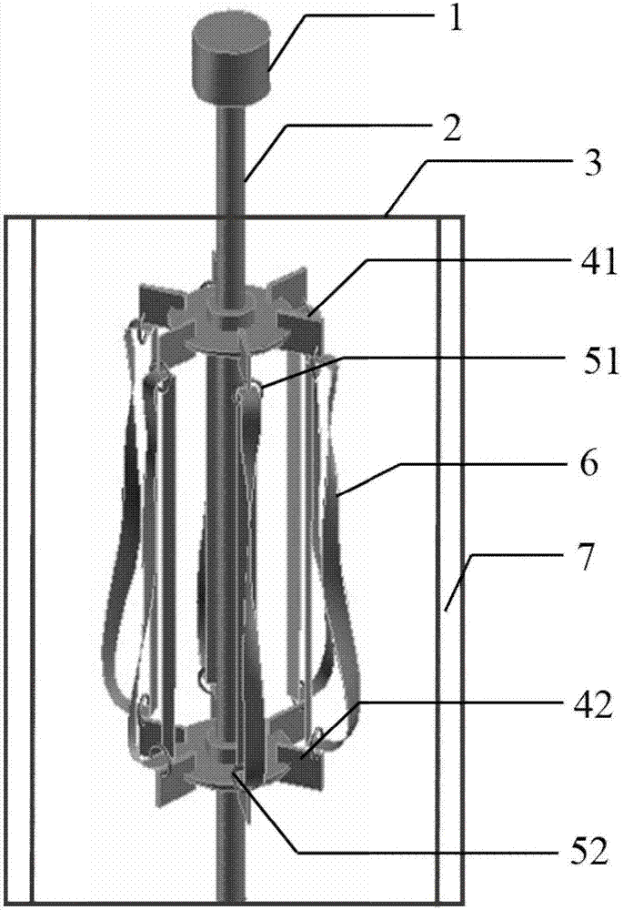
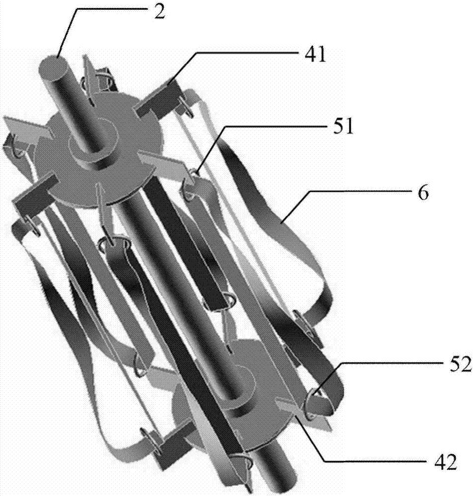
[0037] A rigid-flexible combined stirring paddle that improves fluid mixing effect, is characterized in that: comprise stirring shaft 2, and rigid paddle I41, rigid paddle II42, several rings I51, several rings II52, several flexible Mobius strips 6 . The number of blades of the rigid stirring paddle I41 and the rigid stirring paddle II42 is equal.

[0038] The node on the stirring shaft 2 with fixed rigid stirring paddle I41 is marked as node A, and the node on the stirring shaft 2 with fixed rigid stirring paddle II42 is marked as node B.

[0039] The node A is fixed with a disc body A, and one end of several rigid paddles is fixed around the disc body A. That is, a number of rigid paddles are radially distributed on node A of the stirring shaft 2 . In the embodiment, several rigid paddles are evenly distributed around the stirring shaft 2 .

[0040] The node B is fixed with a disc body B, and one end of several rigid paddles is fixed around the disc body B. That is, a n...

Embodiment 2

[0044] The main structure of this embodiment is the same as embodiment 1, further:

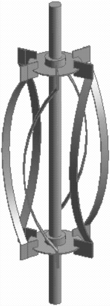
[0045] The diameter of rigid stirring paddle I41 and rigid stirring paddle II42 is equal. That is, the diameter of the rigid stirring blade I41 is D, and the diameter of the rigid stirring blade II42 is also D. The paddle of rigid paddle I41 is the same size as the paddle of rigid paddle II42.

[0046]It is found through research that when the width of the flexible Mobius strip 6 is too narrow, it is beneficial for the flexible Mobius strip 6 to twist or vibrate, but the ability to transfer energy is poor; when the width of the flexible Mobius strip 6 is too large Wide, it is not conducive to twisting or shaking of the flexible Möbius strip 6, but the ability to transmit energy is strong. The width of the flexible Möbius strip 6 is d, and when d is 1 / 40-1 / 10 of D, the system can obtain a better mixing effect.

[0047] The distance between the blade lower edge of the rigid paddle I41 and the...


PUM


Abstract

The present invention relates to a rigid-flexible combined paddle for enhancing the fluid mixing effect, comprising a stirring shaft, a plurality of rigid stirring blades, a plurality of flexible Mobius bands and a plurality of rings. The rigid and flexible combined paddle consists of at least upper and lower layers and is mainly composed of upper and lower rigid stirring blades fixed on a stirring shaft and the flexible Mobius bands connected between the upper and lower rigid stirring blades through the ring. The rigid-flexible combined paddle is driven by the motor to rotate in a stirring tank, and mechanical energy is input to the fluid in the stirring tank to obtain the appropriate flow field of the fluid to strengthen the fluid mixing process. Compared with the prior art, the flexible Mobius strip in the rigid-flexible combined paddle according to the present invention can constantly shake or perform multi-body movement by the interaction between the stirring shaft and the fluid to continuously change the flow direction of the fluid, increase the turbulence of the fluid, enhance the energy transfer process, increase the mixing efficiency of the fluid, and save the cost of the device.

Description

technical field [0001] The invention relates to a stirring paddle in a fluid mixing device in a chemical production process. Background technique [0002] Mechanically stirred reactors are widely used in chemical, metallurgical and other process industries. They are the core equipment of related production processes, and their economic efficiency is closely related to fluid mixing performance. With the progress and development of chemical technology, stirred reactors are developing in the direction of large-scale and energy-saving. Due to the complex correlation and highly sensitive dependence between the fluid mixing performance, the interface structure of the flow field and the structure of the stirred reactor, the design and scale-up of the stirred reactor still lacks complete theoretical support and relies heavily on experience. According to statistics, the annual loss caused by unreasonable design of stirred reactors in the world is as high as tens of billions of dolla...

Claims


Application Information

Patent Timeline
Patent Type & Authority Applications(China)
IPC IPC(8): B01F7/00B01J19/00
CPCB01J19/0066B01F27/054B01F27/074B01F27/192
Inventor 刘作华谷德银刘培乔陶长元刘仁龙范兴杜军谢昭明许传林李文生唐金晶孔令峰左赵宏杨勇许恢琴张柱杨义
Owner CHONGQING UNIV
Why Eureka
Try Eureka