Telescopicanaesthetic laryngoscope

An anesthesia laryngoscope, telescopic technology, applied in the field of medical equipment, can solve the problems that a single laryngoscope cannot meet the needs of actual use, cannot change the outer dimension of the laryngoscope, damage to teeth and soft tissues, etc., and achieve the function of laryngoscopy Need, simplify operation requirements, reduce the effect of discomfort

Active Publication Date: 2017-10-24
SHANGHAI PUDONG HOSPITAL
View PDF7 Cites 7 Cited by
  • Summary
  • Abstract
  • Description
  • Claims
  • Application Information

AI Technical Summary

Problems solved by technology

[0003] The laryngoscopes of the prior art have the following disadvantages when inspecting the larynx: 1. The base of the tongue and the epiglottis need to be directly lifted with a laryngoscope, which usually requires hospitalization under general anesthesia. Fixed, it will inevitably lead to tooth and soft tissue damage when inserting, adjusting the position of the laryngoscope and lifting the mirror. Although it has been continuously improved and adopted a flexible material structure design, it is still made around the structural principle of the laryngoscope. Patients also feel uncomfortable under the condition of mucosal surface anesthesia; 2. The structure of the laryngoscope is fixed. Although the bending limit angle of the laryngoscope can be changed by using flexible or plastic materials, the outer dimension of the laryngoscope cannot be changed. When patients undergo laryngeal examination, laryngeal blades of different sizes will be used due to the different sizes of the larynx, so a single laryngeal blade cannot meet different actual needs
3. During the inspection process, the medical personnel need to hold the operation and maintain stability all the time. At the same time, they also need to be distracted to observe the image of the monitor. The operability requirements are relatively high and it is inconvenient to use

Method used


Image

  • Telescopicanaesthetic laryngoscope
  • Telescopicanaesthetic laryngoscope
  • Telescopicanaesthetic laryngoscope

Examples


Embodiment Construction

[0029] In order to make the object, technical solution and advantages of the present invention clearer, the present invention will be further described in detail below in conjunction with the accompanying drawings.

[0030] It should be noted that, unless otherwise specified, the technical terms or scientific terms used in this application shall have the usual meanings understood by those skilled in the art to which the present invention belongs.

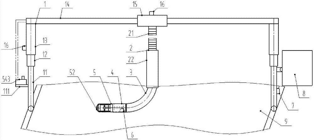
[0031] In the description of the present application, it should be understood that the orientations or positional relationships indicated by the terms "upper", "lower", "left", "right" etc. are based on the attached figure 1 The orientation or positional relationship shown, the orientation or positional relationship indicated by the term "front" is based on the attached figure 1 The "left" shown, the term "rear" indicates the orientation or positional relationship is based on the attached figure 1 The "right" shown is only for the ...


PUM


Abstract

The invention discloses a telescopic anaesthetic laryngoscope. The telescopic anaesthetic laryngoscope comprises a support and a laryngoscope assembly. The support has the effect of hanging the laryngoscope assembly. During the laryngeal examination, an operator does not need to operate by hands all the time. The laryngoscope assembly comprises a plastic and hollow arc section, a connection pipe detachably connected with the front end of the arc section and a visual sleeve member internally sleeving the connection pipe. The visual sleeve member is driven by a driving mechanism to axially slide along an inner cavity of the connection pipe to stretch out and retract. The visual sleeve member can also be adjusted to different lengths for use. A plastic circular-shaped sheath structure is employed so that the needs of application for different ages of patients are met. Meanwhile, the expansion and contraction principle of multiple air bags of two extension members is utilized for effectively supporting the laryngeal. Therefore, an endoscope can conveniently irradiate and carry out imaging operation. The air bags flexibly contact the laryngeal on multiple surfaces in a radial direction, thereby greatly reducing discomfort of the patients. Operation requirements are simplified and lowered. The need of the patients for application of laryngeal examination is effectively satisfied.

Description

technical field [0001] The invention relates to the technical field of medical instruments, in particular to a retractable anesthesia laryngoscope. Background technique [0002] Due to the deep position of the larynx and its complicated physiological structure, it cannot be directly seen. In medical examination of the larynx, a laryngoscope is often needed. Laryngoscopy can provide a detailed understanding of the abnormality of the laryngeal structure, clarify the location and scope of the lesion, and perform a biopsy of the lesion if necessary. [0003] The laryngoscopes of the prior art have the following disadvantages when inspecting the larynx: 1. The base of the tongue and the epiglottis need to be directly lifted with a laryngoscope, which usually requires hospitalization under general anesthesia. Fixed, it will inevitably lead to tooth and soft tissue damage when inserting, adjusting the position of the laryngoscope and lifting the mirror. Although it has been contin...

Claims


Application Information

Patent Timeline
Patent Type & Authority Applications(China)
IPC IPC(8): A61B1/267A61M16/01A61M16/04
CPCA61B1/00131A61B1/267A61M16/01A61M16/04A61M16/0488
Inventor 张南南郭晓翠
Owner SHANGHAI PUDONG HOSPITAL
Why Eureka
Try Eureka