Reinforcing steel bar cutting machine

A cutting machine and steel bar technology, applied in the field of steel bar cutting equipment, can solve the problems of rough cutting edge of metal circular saw cutting knife, fast loss of grinding wheel cutting blade, high production cost, etc., achieve good self-sharpening, convenient transportation and movement, and improve efficiency effect

Pending Publication Date: 2017-10-24
CHENGDU HANDAO TECH CO LTD
View PDF8 Cites 0 Cited by
  • Summary
  • Abstract
  • Description
  • Claims
  • Application Information

AI Technical Summary

Problems solved by technology

Among them, the cutting life of the metal circular saw blade is significantly higher than that of the grinding wheel cutting blade, and it can be recycled after being scrapped, but the cutting edge of the metal circular saw blade is rough and has burrs; while the cutting edge of the grinding wheel cutting blade is neat and free of burrs, but the grinding wheel cutting The blade loss is fast, the production cost is high, and the cutting blade of the grinding wheel with the same diameter is thicker than the metal saw blade, the incision is large, and the waste is serious. Both cutting knives are insufficient.

Method used


Image

  • Reinforcing steel bar cutting machine
  • Reinforcing steel bar cutting machine
  • Reinforcing steel bar cutting machine

Examples


Embodiment Construction

[0022] The present invention will be further described below with reference to the accompanying drawings and examples, and the implementation of the present invention includes but not limited to the following examples.

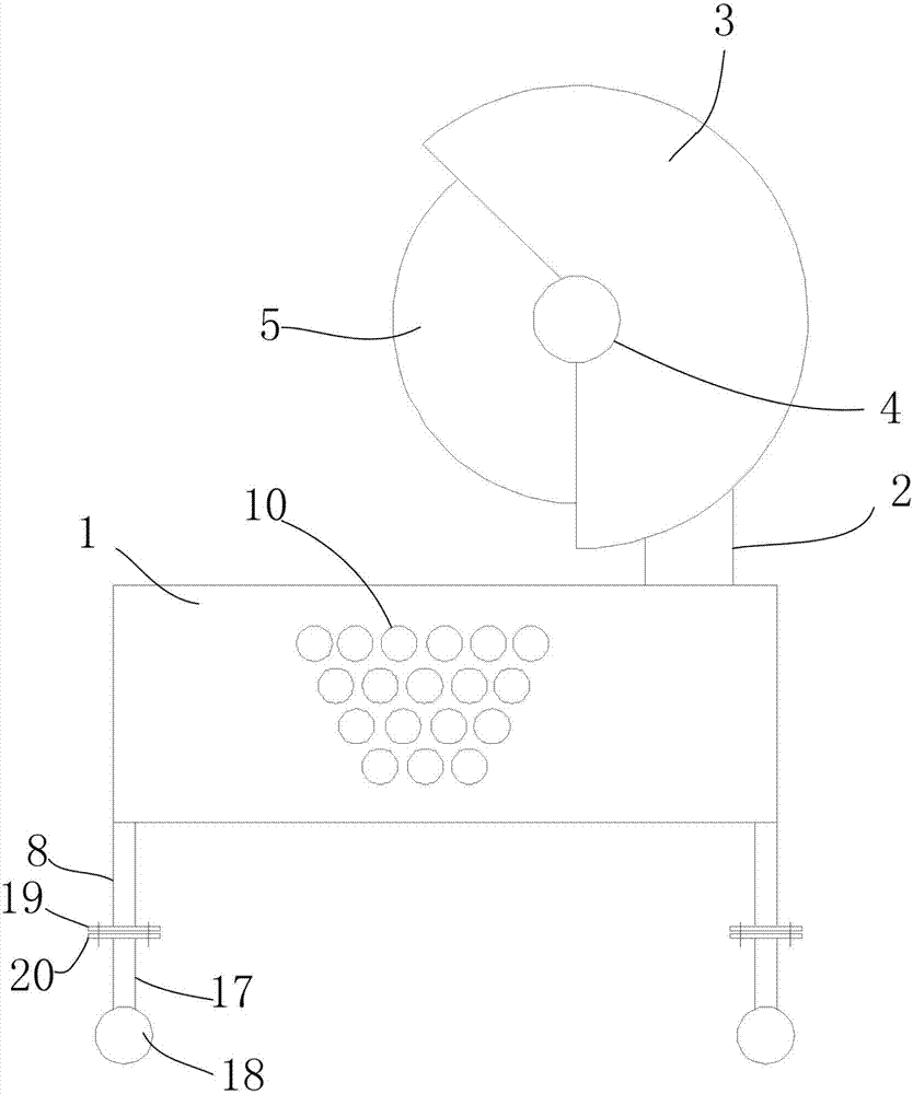
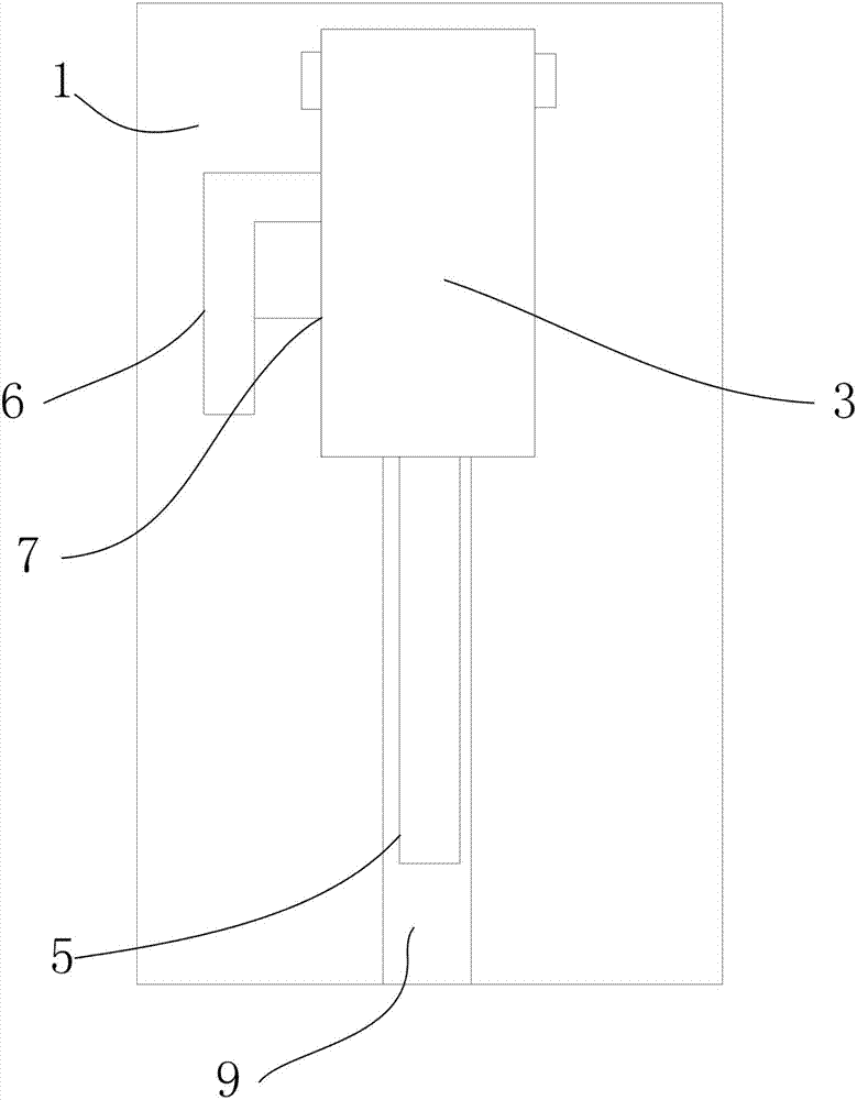
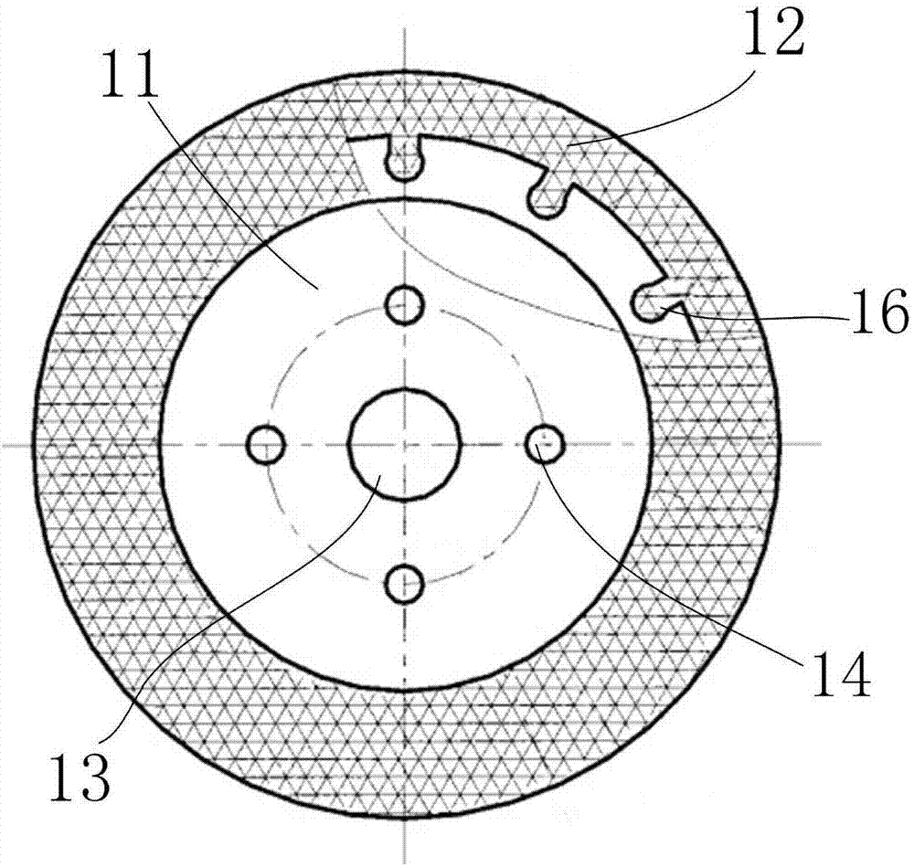
[0023] Such as Figure 1~4 As shown, a steel bar cutting machine includes a base 1, a support 2, a detachable cover 3, a central shaft 4, a cutting knife 5, a handle 6, a driving motor 7, a supporting leg 8, and a moving mechanism; wherein, the supporting There are four legs 8, the machine base 1 is longitudinally provided with a cutting groove 9, the machine base 1 is provided with a circular through hole 10 penetrating transversely, the circular through holes 10 are multiple and arranged in an inverted trapezoidal shape, and the cutting knife 5 consists of alloy steel The disc-shaped cutter body 11 made of high-quality material and the grinding wheel 12 arranged on the outer edge of the cutter body 11 and sintered and connected with the cutter body 11 as a w...


PUM


Abstract

The invention discloses a reinforcing steel bar cutting machine comprising a machine seat, a support, a detachable machine cover, a center shaft, a cutter, a handle, a drive motor, four supporting legs and a moving mechanism. The support is installed at the back end of the machine seat. The detachable machine cover is installed on the support. The center shaft is arranged at the center of the detachable machine cover. The cutter is installed inside the detachable machine cover. The handle is installed on the left side of the detachable machine cover. The drive motor is installed at the lower end of the handle and connected with the center shaft. The four supporting legs are installed at the bottom end of the machine seat. The moving mechanism is installed at the lower ends of the supporting legs. The machine seat is longitudinally provided with a cutting groove. The machine seat is provided with multiple round through holes arranged in a reversed-trapezoid shape, wherein the round through holes transversely penetrate through the machine seat. The cutting groove is matched with the cutter. The cutter comprises a round-disk-shaped cutter body and a grinding wheel, wherein the round-disk-shaped cutter body is made of alloy steel, the grinding wheel is arranged on the edge of the cutter body, and the grinding wheel and the cutter body are connected into a whole through sintering. The outer circumference of the cutter body is provided with convex portions and connection grooves. The grinding wheel is provided with concave-convex structures matched with the convex portions and the connection grooves.

Description

technical field [0001] The invention relates to the field of steel bar cutting equipment, in particular to a steel bar cutting machine. Background technique [0002] A steel bar cutter is a tool used to cut steel bars. Generally, there are fully automatic steel cutting machines and semi-automatic steel cutting machines. It is one of the necessary equipment for steel bar processing, and it is mainly used for cutting steel bars to fixed length in housing construction, bridges, tunnels, power stations, large-scale water conservancy and other projects. Compared with other cutting equipment, the steel bar cutting machine has the characteristics of light weight, low energy consumption, reliable operation and high efficiency. Therefore, it has been widely used in mechanical processing and small rolling mills in recent years, and has played an important role in various fields of national economic construction. role. [0003] Existing steel bar cutting machines are all single cutt...

Claims


Application Information

Patent Timeline
Patent Type & Authority Applications(China)
IPC IPC(8): B21F11/00
CPCB21F11/00
Inventor 王蓉
Owner CHENGDU HANDAO TECH CO LTD
Why Eureka
Try Eureka