Production process of shuttlecock heads

A production process and badminton technology, applied in the field of badminton equipment, can solve problems such as unstable quality distribution of badminton ball heads, inability to effectively ensure the quality stability of ball heads, and achieve the effect of ensuring uniformity

Active Publication Date: 2017-10-24
安徽明亮面业股份有限公司
View PDF7 Cites 7 Cited by
  • Summary
  • Abstract
  • Description
  • Claims
  • Application Information

AI Technical Summary

Problems solved by technology

However, the above two methods cannot guarantee that the mass distribution of badminton heads produced each time is unstable, and cannot effectively guarantee the stability of the quality of the badminton heads.

Method used


Image

  • Production process of shuttlecock heads
  • Production process of shuttlecock heads
  • Production process of shuttlecock heads

Examples


Embodiment 1

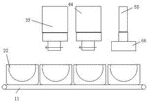
[0026] Such as figure 1 Shown is a production system for badminton heads, including a transmission mechanism, a batching mechanism, a compacting mechanism and a glue injection machine arranged above the transmission mechanism;

[0027] The transmission mechanism includes a ball mold 22 and a vibrating conveyor 11; the ball mold 22 is a finished product and is purchased; before use, the ball mold 22 is placed in a heating mechanism (in this embodiment, it can be a muffle furnace, a box type high temperature furnace or oven), used to heat the ball mold 22 to a certain temperature; the ball mold 22 is placed on the vibration conveyor 11, and can move with the vibration conveyor 11; in order to ensure that the ball mold 22 will not be caused by Vibration causes displacement deviation. The vibration conveyor 11 is provided with a ball head mold 22 installation groove, and the ball head mold 22 is located in the installation groove.

[0028] The batching mechanism comprises a feede...

Embodiment 2

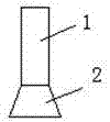
[0032] The difference from Example 1 is that, as Figure 2-3 The glue injection machine shown includes a glue feeding mechanism 1 and a glue melting mechanism 2 arranged vertically:

[0033] The glue delivery mechanism 1 includes a glue delivery inlet and a glue delivery outlet; in this embodiment, the glue delivery mechanism 1 can use a glue delivery gun in the prior art, but here the end of the glue delivery gun is not equipped with a heating device, and only realizes uniform delivery of glue role;

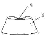
[0034] The glue melting mechanism 2 includes a heating body 3; the heating body 3 is arranged on the glue feeding outlet side of the glue feeding mechanism 1, and the heating body 3 is insulated between the glue feeding mechanism 1 (there is no heat between the heating body 3 and the glue feeding mechanism 1 in this embodiment). In contact, a heat insulating layer / insulation layer can also be laid between the heating body 3 and the glue feeding mechanism 1), the heating body 3 ...


PUM

PropertyMeasurementUnit
Thicknessaaaaaaaaaa

Abstract

The invention belongs to the field of shuttlecock equipment and the field of shuttlecock head production devices, and particularly relates to a production process of shuttlecock heads. The production process comprises the following steps that firstly, the inner surfaces of shuttlecock head molds are coated with a lubricating agent, and a heating device is adopted for preheating the shuttlecock head molds; secondly, the multiple preheated shuttlecock head molds are put on a vibration conveyor at equal intervals; thirdly, a wood block feeder is started, and wood blocks are fed into the shuttlecock head molds; fourthly, a polyurethane particle feeder is started; fifthly; a compression cylinder does lifting and contraction motion, and the wood blocks and polyurethane elastomer particles in the molds are compressed through a compaction block; and sixthly, a glue injection machine is started, glue injection is firstly carried out on the wood blocks and the polyurethane elastomer particles along the inner walls of the shuttlecock head molds, and then glue injection is carried out on the surfaces of the wood blocks and the surfaces of the polyurethane elastomer particles. According to the production process, streamline production can be carried out on the shuttlecock heads, and the stability of the quality of the shuttlecock heads produced on an assembly line can be guaranteed.

Description

technical field [0001] The invention belongs to the field of badminton equipment and the field of production devices for badminton heads, in particular to a production process for badminton heads. Background technique [0002] The International Badminton Federation has strict regulations on the weight of badminton. The weight of the ball head is generally controlled within 2.6g, except for the feathers, coils, and glue. For example, if 16 pieces of wool weigh 1.8g, then it is more appropriate to use 2.3g of ball heads. Add base glue and thread glue to make balls of about 5g. In actual production, ball heads are classified according to the standard of each difference of 0.04g. [0003] During the use of the shuttlecock, the motion requirements of the shuttlecock in the air are quite high, and the shuttlecock is required to generate greater power to reach a certain distance. Due to these requirements, certain adjustments to the weight distribution of the badminton head are re...

Claims


Application Information

Patent Timeline
IPC IPC(8): B29C43/06B29C43/36B29C43/32B29C33/64B29L31/52
CPCB29C33/64B29C43/06B29C43/32B29C43/36B29L2031/52
Inventor 陈道根
Owner 安徽明亮面业股份有限公司
Why Eureka
Try Eureka