Spiral conveying device with mud filtering function

A technology of screw conveying device and function, applied in the field of screw conveying device, can solve the problems such as difficulty in selecting screen mesh, easy blocking of screen, long cycle and so on.

Active Publication Date: 2017-10-24
YANGTZE UNIVERSITY
View PDF14 Cites 2 Cited by
  • Summary
  • Abstract
  • Description
  • Claims
  • Application Information

AI Technical Summary

Problems solved by technology

[0004] ① It is difficult to select the mesh of vibrating screen and dryer screen, and the screen is ea...

Method used


Image

  • Spiral conveying device with mud filtering function
  • Spiral conveying device with mud filtering function
  • Spiral conveying device with mud filtering function

Examples


Embodiment Construction

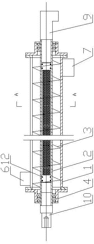
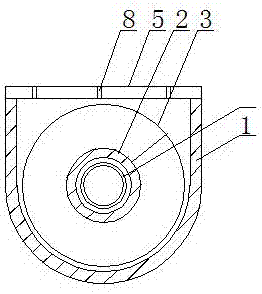
[0026] The screw conveying device with mud filtering function includes a trough 1, a drive shaft 2 and a blade 3. The trough 1 is equipped with a drive shaft 2 through a symmetrically arranged bearing seat 4, and the drive shaft 2 is screwed with blades 3 to Promote materials forward during work. The cross section of the trough 1 of the screw conveying device is a U-shaped body, a cover plate 5 is arranged on the trough 1 and the cover plate 5 is evenly distributed with air holes 8. A feed port 6 is provided at the top of one end of the trough 1, and a discharge port 7 is provided at the bottom of the other end of the trough 1. One end of the drive shaft 2 extends to the outer end of the front part of the trough 1, and the drive shaft 2 extending to the outer end of the front part of the trough 1 is sealed with a rotating head 9 to connect the vacuum device during work; so that the trough 1 Negative pressure is formed inside. The other end of the drive shaft 2 extends to the ...


PUM


Abstract

The invention relates to a spiral conveying device, in particular to the spiral conveying device with a mud filtering function. The spiral conveying device comprises a material trough, a transmission shaft and blades. One end of the transmission shaft extends to the outer end of the front part of the material trough, and the transmission shaft which extends to the outer end of the front part of the material trough is provided with a rotating head in a sealing mode; and the other end of the transmission shaft extends to the outer end of the tail part of the material trough, and the transmission shaft which extends to the outer end of the tail part of the material trough is connected with a power motor through a coupling. According to the spiral conveying device, during the conveying process of drilling mud, solid and liquid separating for the drilling mud can be effectively conducted; the problems that the existing solid controlling device is high in purchasing cost and long in period of separating process, a sieve is likely to be blocked, and maintenance and repair are inconvenient are solved; by the spiral conveying device, the solid and liquid separating efficiency is significantly improved; meanwhile, the spiral conveying device has the characteristics of being low in cost, short in process period and easy to maintain and repair, and has positive popularizing meanings for reducing the purchasing cost of the existing solid controlling device and improving solid and liquid separating of the drilling mud.

Description

Technical field [0001] The invention relates to a screw conveying device, in particular to a screw conveying device with mud filtering function. Background technique [0002] During the drilling of oil and gas wells, the drilling fluid (mud) returned to the surface from the wellhead contains a large amount of drill cuttings, barite and other large solid particles. Under normal circumstances, solids control equipment is used to effectively separate the mud from solid and liquid to retain the liquid and useful solid components, so that the treated drilling fluid (mud) can be reused to reduce drilling costs and protect the environment. [0003] In recent years, the solids control system, from drilling fluid circulation tanks to solids control equipment, has been greatly improved technically, and the technological process has become more reasonable. The purification process of drilling fluid solids control equipment is roughly as follows: wellhead (returned drilling fluid) → drilling ...

Claims


Application Information

Patent Timeline
IPC IPC(8): E21B21/06F04D3/02F04D29/70F04D7/00
CPCE21B21/065F04D3/02F04D7/00F04D29/708Y02P70/10
Inventor 马卫国吴霁薇阳婷陈婷
Owner YANGTZE UNIVERSITY
Why Eureka
Try Eureka