
A manufacturing process of an array substrate and a manufacturing process of a display panel

An array substrate and substrate layer technology, applied in the field of manufacturing process and display panel manufacturing process, can solve the problems of complex TFT glass topography, uneven display brightness, affecting the uniformity of alignment film thickness, etc., to achieve uniform thickness and reduce uneven brightness. Effect

Active Publication Date: 2020-05-12
TCL CHINA STAR OPTOELECTRONICS TECH CO LTD
View PDF6 Cites 0 Cited by
  • Summary
  • Abstract
  • Description
  • Claims
  • Application Information

AI Technical Summary

Problems solved by technology

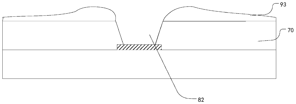
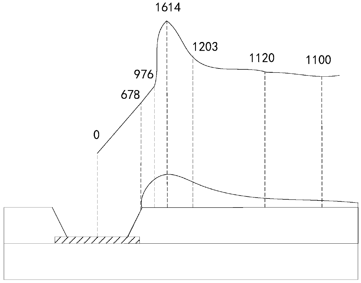
[0004] With the development of technologies such as COA (Color filter On Array, the color photoresist layer is prepared on the array substrate), the multi-via design leads to complex topography of the TFT glass, and the PI liquid cannot flow into the via holes, causing the PI liquid to accumulate around the via holes. Affect the uniformity of the film thickness of the alignment film, which in turn leads to uneven brightness of the display

Method used


Image

  • A manufacturing process of an array substrate and a manufacturing process of a display panel
  • A manufacturing process of an array substrate and a manufacturing process of a display panel
  • A manufacturing process of an array substrate and a manufacturing process of a display panel

Examples


Embodiment Construction

[0046] Specific structural and functional details disclosed herein are representative only and for purposes of describing example embodiments of the present invention. This invention may, however, be embodied in many alternative forms and should not be construed as limited to only the embodiments set forth herein.

[0047] In describing the present invention, it is to be understood that the terms "central", "lateral", "upper", "lower", "left", "right", "vertical", "horizontal", "top", The orientation or positional relationship indicated by "bottom", "inner", "outer", etc. is based on the orientation or positional relationship shown in the drawings, and is only for the convenience of describing the present invention and simplifying the description, rather than indicating or implying the referred device Or elements must have a certain orientation, be constructed and operate in a certain orientation, and thus should not be construed as limiting the invention. In addition, the te...


PUM

PropertyMeasurementUnit
thicknessaaaaaaaaaa
thicknessaaaaaaaaaa

Abstract

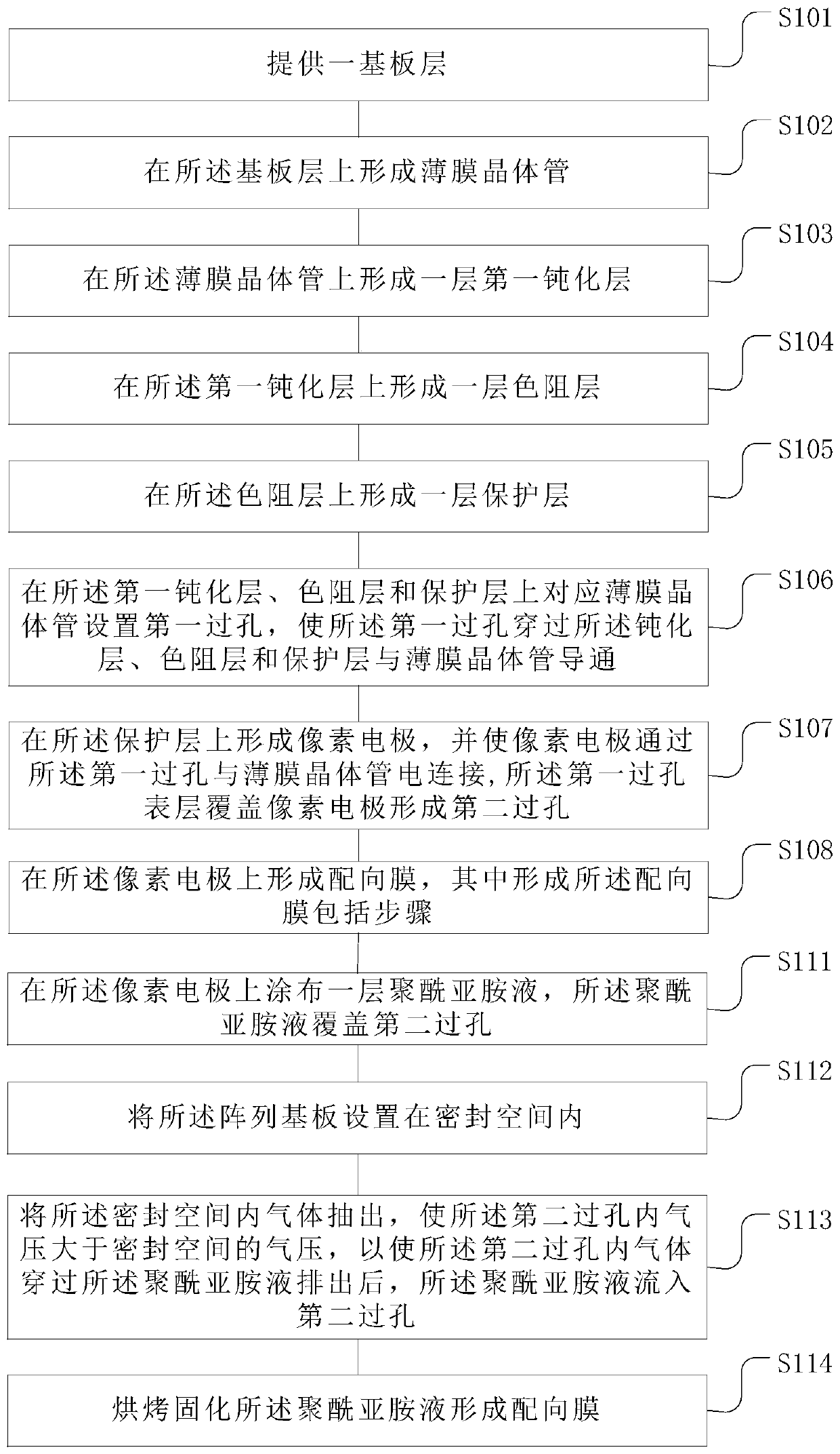
The invention provides procedures for manufacturing array substrates and display panels. The procedure for manufacturing the array substrates includes sequentially forming substrate layers, thin film transistors, first passivation layers, color resistance layers and protective layers; forming first via holes in the first passivation layers, the color resistance layers and the protective layers; forming pixel electrodes on the protective layers and covering the pixel electrodes with surface layers of the first via holes to form second via holes; forming alignment films on the pixel electrodes, to be more specific, coating a layer of polyimide solution on each pixel electrode, covering the second via holes with the polyimide solution, placing the array substrates in sealed spaces, exhausting air in the sealed spaces, allowing the internal air pressures of the second via holes to be higher than the air pressures of the sealed spaces, allowing the polyimide solution to flow into the second via holes after air in the second via holes flows through the polyimide solution and then is exhausted, and baking and curing the polyimide solution to form the alignment film. The first via holes correspond to the thin film transistors. The procedures have the advantages that the alignment films are similarly uniform at the peripheral edges of the second via holes, and the occurrence rates of defects such as uneven brightness of the alignment films can be reduced.

Description

【Technical field】 [0001] The present invention relates to the field of display technology, in particular to a manufacturing process of an array substrate and a manufacturing process of a display panel. 【Background technique】 [0002] Existing displays mainly include liquid crystal (Liquid Crystal Display, LCD) displays and OLED (Organic Light Emitting Diode, OLED) displays. [0003] In the TFT (Thin Film Transistor, thin film transistor) LCD process, PI (Polyimide, polyimide) liquid is sprayed on the conductive glass and then baked to form an alignment film, which can provide a pre-tilt angle for the liquid crystal molecules, so that the liquid crystal molecules The direction of rotation is the same. The uniformity of the film thickness of the alignment film directly affects the display effect of the TFT LCD. [0004] With the development of technologies such as COA (Color filter On Array, the color photoresist layer is prepared on the array substrate), the multi-via desig...

Claims


Application Information

Patent Timeline
Patent Type & Authority Patents(China)
IPC IPC(8): G02F1/1337G02F1/1362
CPCG02F1/133723G02F1/136227
Inventor 朱清永
Owner TCL CHINA STAR OPTOELECTRONICS TECH CO LTD
Learn More