Simplified pre-charging synchronous switch circuit of switched capacitor set

A technology of switching capacitors and pre-charging circuits, which is applied in the direction of circuit devices, AC network circuits, electrical components, etc., can solve the problems of complex structure, difficult work, re-ignition, etc., and achieve the effect of simple circuit structure design

Inactive Publication Date: 2017-10-27
北京馨容纵横科技发展有限公司
View PDF10 Cites 2 Cited by
  • Summary
  • Abstract
  • Description
  • Claims
  • Application Information

AI Technical Summary

Problems solved by technology

The pre-charging technology produces different pre-charging circuit structures. The pre-charging switch circuits of various structures have different application ranges and advantages and disadvantages. Typical invention patents: "A device for switching capacitor banks based on synchronous pre-charging switches", Patent No.: 201210468939.1, using a unipolar synchronous switch, a bipolar synchronous switch or 3 unipolar synchronous switches, 3 pre-charging circuits, and 3 position feedback circuits to achieve fast switching without inrush current, but this invention also exists When the third unipolar synchronous switch is closed, due to the voltage change on the capacitor, it is difficult to find the contact voltage of the third synchronous switch to be zero every time, resulting in occasional impacts on the switching current, and at the same time, the pre-charging circuit is over Many, complex structure, with the pre-charging circuit, the capacitor bank has a pre-charging voltage when the synchronous switch is turned on, and the capacitor bank is not separated from the grid power supply
Utility model patent: "A 2-control 3 simplified pre-charging synchronous switch circuit for switched capacitor banks", patent number: 201520433809.3, than invention patent: "A 2-control 3 pre-charge phase-controlled switch circuit for switched capacitor banks" , Patent No.: 200910076776.0, great progress has been made, and the circuit structure is simplified. Among the two synchronous switches K1 and K2, only one synchronous switch K2 is equipped with a pre-charging circuit, and the other synchronous switch K1 is not equipped with a pre-charging circuit. The charging circuit is simplified from two to one, the action speed is fast, there is no current impact, the voltage of the switch contact is low when the switch is cut off, and there is no more than 3 times the line voltage, and the actions of the two synchronous switches are operated separately, and there are strict Phase sequence, the shortcoming circuit form is 2-control 3 type, a switch contact is saved in the three-phase circuit, so that the voltage of the switch contact is still high, which is line voltage, and it is easy to cause re-ignition when working in a medium-voltage system. Medium voltage system work
The disadvantage is that there are two pre-charging circuits and an auxiliary switch in the circuit. When the auxiliary switch is turned on, it is required to bear the voltage of the main circuit. In the conventional central cabinet (KN28 cabinet) or ring network cabinet, only one three-pole circuit breaker or For a three-pole contactor, if a single-pole auxiliary switch is added, the existing cabinet needs to be redesigned, and the work is very difficult

Method used


Image

  • Simplified pre-charging synchronous switch circuit of switched capacitor set
  • Simplified pre-charging synchronous switch circuit of switched capacitor set
  • Simplified pre-charging synchronous switch circuit of switched capacitor set

Examples


Embodiment Construction

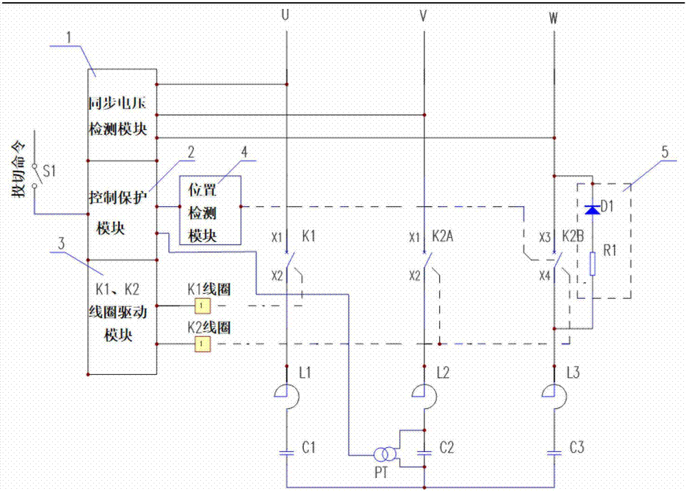
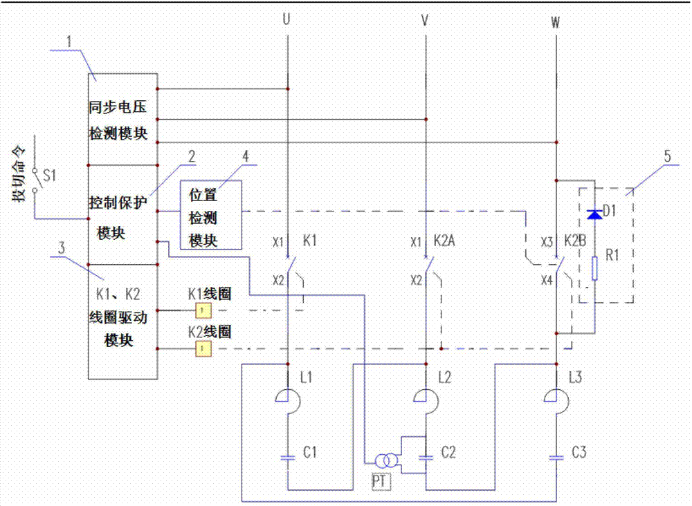
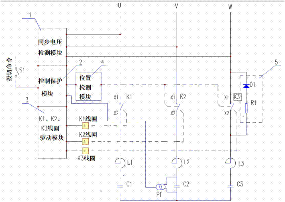
[0022] please see figure 1 It is: a circuit diagram of an embodiment of a simplified pre-charging synchronous switch circuit of a switching capacitor bank.

[0023] The synchronous switch is composed of a unipolar synchronous switch K1 and a bipolar synchronous switch K2, one contact K2B of the bipolar synchronous switch K2 is configured with a pre-charging circuit 5, and the other contact K2A of the bipolar synchronous switch K2 The contacts of the unipolar synchronous switch K1 and K1 are not equipped with a pre-charging circuit. The input terminals of the unipolar synchronous switch K1 and the bipolar synchronous switch K2 are connected to the three-phase 10kV grid power supply, and the output terminals are connected to the capacitor bank. The reactor L of the capacitor bank The capacitor C is connected in a star-shaped connection type, and the two ends of the capacitor of the phase where the contact K2A of the two-pole synchronous switch K2 is placed are the discharge coil...


PUM


Abstract

The invention discloses a simplified pre-charging synchronous switch circuit of the switched capacitor set. A simplified pre-charging electric synchronization switch circuit of a switched capacitor set consists of a one-pole synchronous switch and a two-pole synchronous switch; in the two-pole synchronous switch, only one contact is provided with a pre-charging circuit 5 and a position detection module 4; a circuit is simple and is easy to install in a middle-voltage cabinet; when the synchronous switch is put into a capacitor set, after one single-pole synchronous switch is switched off, pre-charging is performed on the capacitor set through a pre-charging circuit and the two-pole synchronous switch is switched off after charging is done; a single three-pole synchronous switch mode is adopted; three poles of the synchronous switch synchronously produce current and have no surge; when the capacitor set is cut off, three single-pole synchronous switch modes are adopted; three contacts of the synchronous switch are switched on at a zero-crossing point; a switching fast time interval achieves a second level; and power grid voltage is separated from a capacitor set when the synchronous switch is switched on.

Description

technical field [0001] The invention relates to a simplified pre-charging synchronous switch circuit for switching capacitor banks, which is used in the power quality control project of the power grid, and can realize fast non-impact current input to the capacitor bank and cut off when the current crosses zero, and belongs to the reactive power of the power system. Compensation and harmonic filtering technology field. Background technique [0002] In synchronous switch technology, there are conventional synchronous switches, also known as phase selection switches or phase control switches, and pre-charge switches. The advantages and disadvantages of conventional synchronous switching and pre-charged synchronous switching technology in existing synchronous switches are analyzed. [0003] The conventional synchronous switch is three unipolar switches with zero voltage on the switch contacts, and the power supply voltage is zero when input, there is no current impact, the curr...

Claims


Application Information

Patent Timeline
Patent Type & Authority Applications(China)
IPC IPC(8): H02J3/18
CPCH02J3/1835Y02E40/30
Inventor 杨建宁
Owner 北京馨容纵横科技发展有限公司
Why Eureka
Try Eureka