Combined Substrate Holder for Microwave Plasma Chemical Vapor Deposition Equipment

A technology of chemical vapor deposition and microwave plasma, applied in the direction of gaseous chemical plating, metal material coating process, coating, etc., can solve the problem of microwave power, temperature, air pressure, unstable air flow, and samples falling under the equipment lifting platform , affecting the use of molybdenum brackets, etc., to achieve the effects of improving accuracy and reliability, reducing production costs, and reducing processing time

Active Publication Date: 2019-09-27
INST OF SEMICONDUCTORS - CHINESE ACAD OF SCI
View PDF11 Cites 0 Cited by
  • Summary
  • Abstract
  • Description
  • Claims
  • Application Information

AI Technical Summary

Problems solved by technology

Moreover, the film layer and the tray have strong adhesion. For example, the adhesion between the diamond film and the molybdenum support is particularly strong, and it is difficult to clean these polycrystalline diamond films at the rings formed on the side wall and the upper surface of the molybdenum support. Affect the subsequent use of molybdenum bracket
In addition, during the experiment, the growth of the molybdenum holder with no small pit in the center often causes the sample to be blown away due to the problem of internal airflow, especially in the process of heating and cooling, microwave power, temperature, air pressure, airflow, etc. are not stable. Stable, flat-centered molybdenum holders often experience sample blow-off
Once the sample is blown away, if it is mild, open the reaction chamber to find the sample and clean it again to continue the experiment. In severe cases, the sample will fall under the lifting platform of the equipment, and the equipment must be disassembled to take out the sample

Method used


Image

  • Combined Substrate Holder for Microwave Plasma Chemical Vapor Deposition Equipment
  • Combined Substrate Holder for Microwave Plasma Chemical Vapor Deposition Equipment
  • Combined Substrate Holder for Microwave Plasma Chemical Vapor Deposition Equipment

Examples


Embodiment Construction

[0030] In order to make the object, technical solution and advantages of the present invention clearer, the present invention will be further described in detail below in conjunction with specific embodiments and with reference to the accompanying drawings. The following description of the embodiments of the present invention with reference to the accompanying drawings is intended to explain the general inventive concept of the present invention, but should not be construed as a limitation of the present invention.

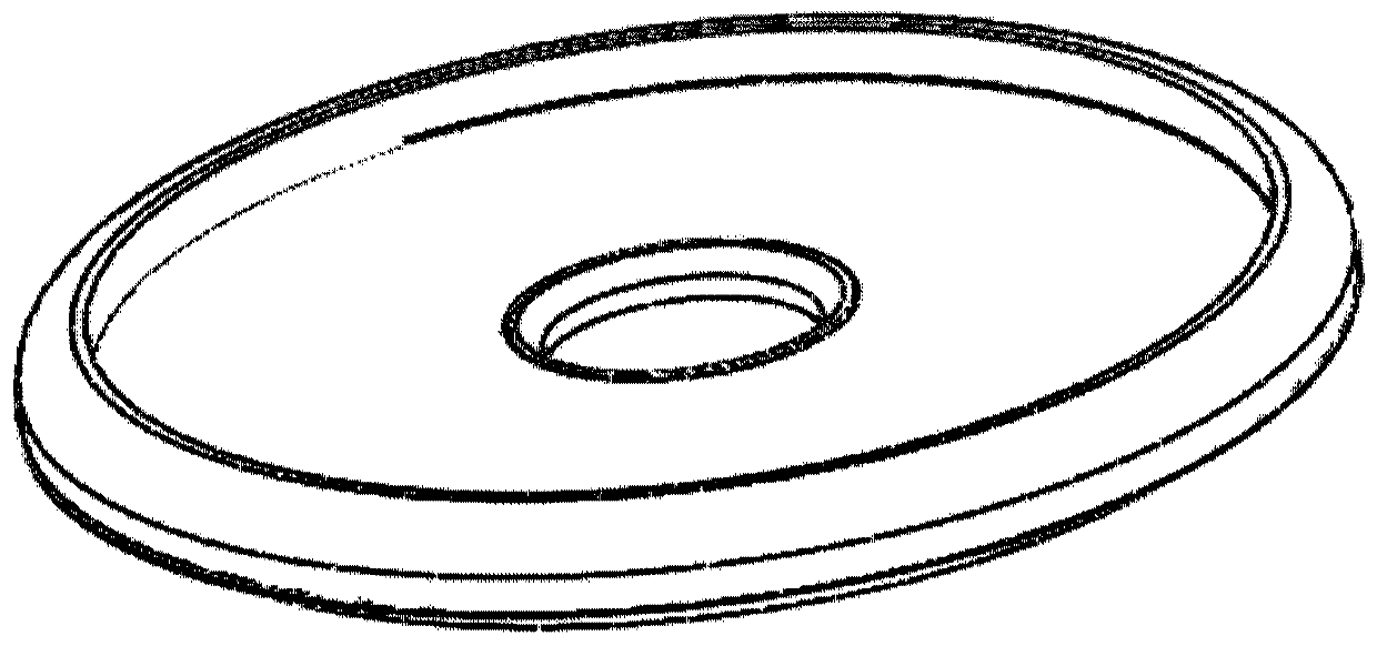
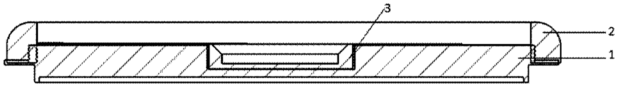
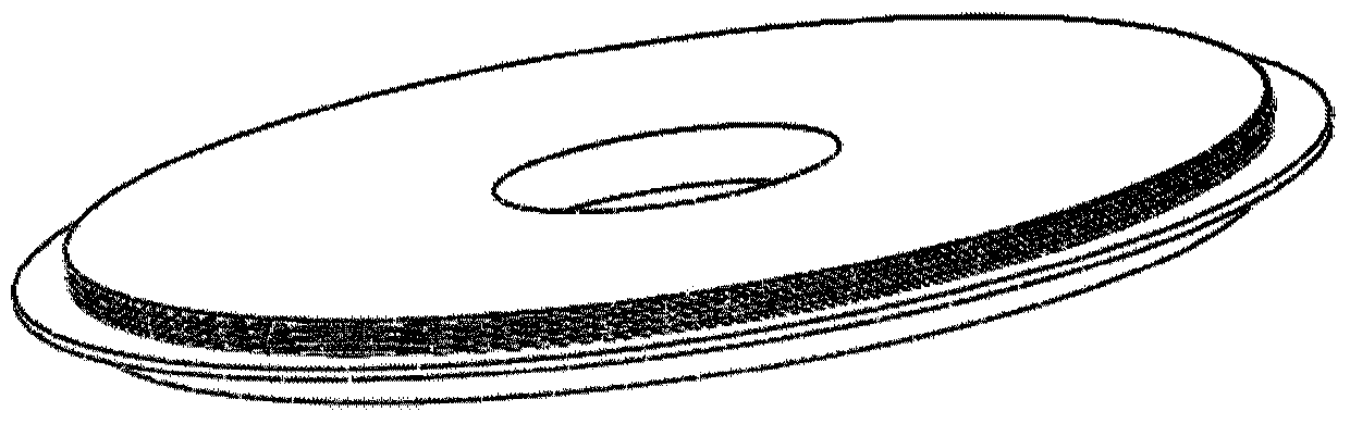
[0031] According to the general inventive concept of the present invention, a combined substrate base for microwave plasma chemical vapor deposition equipment is provided, including:

[0032] The main body of the tray is a disc structure, the outer side of the disc has external threads, and the center of the disc has a groove;

[0033] The outer edge part is a ring structure, and the inner side of the ring has an internal thread matched with the external thread. T...


PUM


Abstract

The invention discloses a combined substrate base for a microwave plasma chemical vapor deposition device. The combined substrate base comprises a tray main body, an outer edge part and an embedded part, wherein the tray main body is of a disc structure; an external thread is arranged on the outer side edge of the disc; a groove is formed in the center of the disc; the outer edge part is of a circular ring structure; an internal thread matched with the external thread is arranged on the inner side edge of the circular ring; an outer ring part is screwed on the tray main body through a matched thread structure; the height position of the outer ring part relative to the tray main body can be changed through controlling the screwing turn number; the embedded part is embedded in the groove; and a pit used for placing a sample is formed in the middle of the embedded part. The combined substrate base adopts a three-section split structure, the structure of a tray can be slightly adjusted, the influence degree of the tray structure on experiments is finely studied, and accuracy and reliability of the experiments are improved.

Description

technical field [0001] The invention relates to the fields of supporting devices and material growth, and further relates to a combined tray, in particular to a combined substrate base for microwave plasma chemical vapor deposition equipment. Background technique [0002] In the process of vapor deposition, especially in the process of plasma chemical vapor deposition (such as MPCVD to prepare CVD single crystal diamond), there are many influencing parameters. Material growth products must be fully studied on the impact of the structure of the tray (such as molybdenum tray) on material growth. [0003] Products that use plasma for material growth, such as diamond, combine excellent properties in physics, chemistry, mechanics, optics, electricity, etc., especially in terms of electrical properties, it has a wide band gap, high loading Carrier mobility, saturated electron drift velocity, high breakdown electric field, low dielectric constant, etc. And because it has the high...

Claims


Application Information

Patent Timeline
Patent Type & Authority Patents(China)
IPC IPC(8): C23C16/458
Inventor 付方彬金鹏王占国
Owner INST OF SEMICONDUCTORS - CHINESE ACAD OF SCI
Why Eureka
Try Eureka