
High-efficiency, electrostatic-prevention and laminated magnetic bead

An anti-static, stacking technology, applied in the direction of preventing/reducing unwanted electric/magnetic influences, circuits, electrical components, etc., can solve problems such as unreasonable graphic structure, coil open circuit failure, poor antistatic effect, etc., to achieve Ensure coil current carrying capacity, reduce coil temperature rise, and enhance anti-mite performance

Inactive Publication Date: 2017-10-31
刘锦花
View PDF6 Cites 4 Cited by
  • Summary
  • Abstract
  • Description
  • Claims
  • Application Information

AI Technical Summary

Problems solved by technology

[0002] High-efficiency anti-static laminated chip magnetic beads are widely used in printed circuit boards, and they are connected in series to the power inlet to filter the input power. Due to the dense electrical equipment in the workplace, the electromagnetic field generated by external electrical equipment is easy to interfere with the magnetic field. The internal coil of the bead makes the undesired clutter of the magnetic bead be brought into the printed circuit board; and when the high-efficiency anti-static laminated chip magnetic bead works in high-frequency current, the internal magnetic core will generate a lot of heat, and the internal In the case of long-term operation of high-frequency current, the coil may be blown due to overheating, resulting in open-circuit failure of the coil; in addition, during the production process of the magnetic beads, the intermediate coil and the end electrode will be short due to the unreasonable internal coil pattern structure. short circuit failure
[0003] In addition, the existing laminated chip magnetic beads have poor antistatic effect, and this problem needs to be solved urgently

Method used


Image

  • High-efficiency, electrostatic-prevention and laminated magnetic bead
  • High-efficiency, electrostatic-prevention and laminated magnetic bead

Examples


Embodiment Construction

[0020] The embodiments of the present invention will be described in detail below with reference to the accompanying drawings, but the present invention can be implemented in various ways defined and covered by the claims.

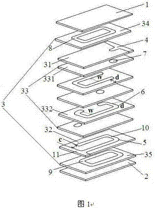
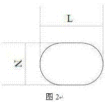
[0021] see Figure 1 ~ Figure 2 A high-efficiency anti-static laminated chip magnetic bead, comprising an upper cover 1, a lower cover 2, and a plurality of superimposed dielectric layers 3 sandwiched between the upper cover 1 and the lower cover 2, the upper dielectric The layer 31 is embedded with an upper lead-out electrode 4 extending to the side of the dielectric layer 3, the lower dielectric layer 32 is embedded with a lower lead-out electrode 5 extending to the side of the dielectric layer 3, and each layer of the intermediate dielectric layer 33 is embedded with an inner The electrode coil 6 or the connection point 7, the intermediate dielectric layer A331 with the connection point 7 and the intermediate dielectric layer B332 with the inner electro...


PUM

PropertyMeasurementUnit
widthaaaaaaaaaa

Abstract

The invention discloses a high-efficiency, electrostatic-prevention and laminated magnetic bead. The high-efficiency, electrostatic-prevention and laminated magnetic bead comprises an upper cover plate, a lower cover plate and a plurality of laminated dielectric layers, wherein the plurality of laminated dielectric layers are sandwiched between the upper cover plate and the lower cover plate, an upper leading-out electrode and a lower leading-out electrode are respectively embedded into the two dielectric layers at an upper end and a lower end and extend to top surfaces or side surfaces of the dielectric layers, internal electrode coils or connection points are arranged in intermediate dielectric layers, the dielectric layers and the dielectric layers with the internal electrode coils are laminated at intervals, the internal electrode coils are non-closed coils with openings, the dielectric layer to which a shielding coil is embedded is sandwiched between the upper cover plate and the upper leading-out electrode dielectric layer or between the lower cover plate and the lower leading-out electrode dielectric layer, the shielding coil is a closed coil without the opening, the shielding coil is not electrically connected with the upper leading-out electrode coil and the lower loading-out electrode coil, an electrostatic-prevention layer is arranged at sides, deviating from each other, of the upper cover plate and the lower cover plate, and a mite resistant layer is also arranged outside the electrostatic-prevention layer. The high-efficiency, electrostatic-prevention and laminated magnetic bead has the advantages of excellent electrostatic resistance performance and high economic value.

Description

technical field [0001] The invention relates to the technical field of laminated chip magnetic beads, in particular to an efficient antistatic laminated chip magnetic bead. Background technique [0002] High-efficiency anti-static laminated chip magnetic beads are widely used in printed circuit boards, and they are connected in series to the power inlet to filter the input power. Due to the dense electrical equipment in the workplace, the electromagnetic field generated by external electrical equipment is easy to interfere with the magnetic field. The internal coil of the bead makes the undesired clutter of the magnetic bead be brought into the printed circuit board; and when the high-efficiency anti-static laminated chip magnetic bead works in high-frequency current, the internal magnetic core will generate a lot of heat, and the internal In the case of long-term operation of high-frequency current, the coil may be blown due to overheating, resulting in open-circuit failu...

Claims


Application Information

Patent Timeline
Patent Type & Authority Applications(China)
IPC IPC(8): H01F27/36H01F27/02H01F27/28H01F27/29
CPCH01F27/022H01F27/2804H01F27/29H01F27/36H01F2027/2809
Inventor 刘锦花
Owner 刘锦花
Learn More