Machining fixture of irregularly-shaped straight slot and machining method

A processing method and through-groove technology, applied in the field of mechanical processing, can solve the problems of difficult to guarantee machining accuracy, low through-groove machining accuracy and positional accuracy, difficult manufacturing and processing, etc., so as to reduce processing costs, improve processing accuracy and processing quality, The effect of improving surface roughness

Active Publication Date: 2017-11-03
GUIZHOU LIYANG INT MFG
View PDF10 Cites 4 Cited by
  • Summary
  • Abstract
  • Description
  • Claims
  • Application Information

AI Technical Summary

Problems solved by technology

[0002] At present, with the development of the manufacturing industry, many small parts that require high machining accuracy are widely used in the aerospace industry. These parts often have certain special uses, so it is necessary to design and process some special-shaped parts on these parts When processing special-shaped through grooves on such parts, due to the design requirements of high machining accuracy, the surface roughness requirement is Ra1.6, resulting in difficulties in manufacturing and processing. If conventional plunge milling, grinding, milling It is difficult to meet the requirements of processing accuracy by other processing methods. For example, when using milling processing method, it is necessary to use a special milling cutter to insert and mill perpendicular to the direction of the special-shaped through groove. Deformation, resulting in low machining accuracy and position accuracy of the through groove, the surface roughness of the through groove does not meet the design requirements, during the process

Method used


Image

  • Machining fixture of irregularly-shaped straight slot and machining method
  • Machining fixture of irregularly-shaped straight slot and machining method
  • Machining fixture of irregularly-shaped straight slot and machining method

Examples


Embodiment Construction

[0027] The technical solution of the present invention will be further described below in conjunction with the accompanying drawings, but the claimed protection scope is not limited to the above;

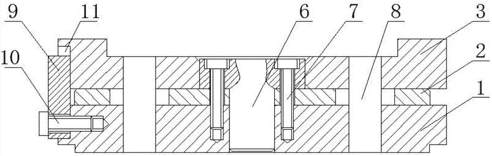
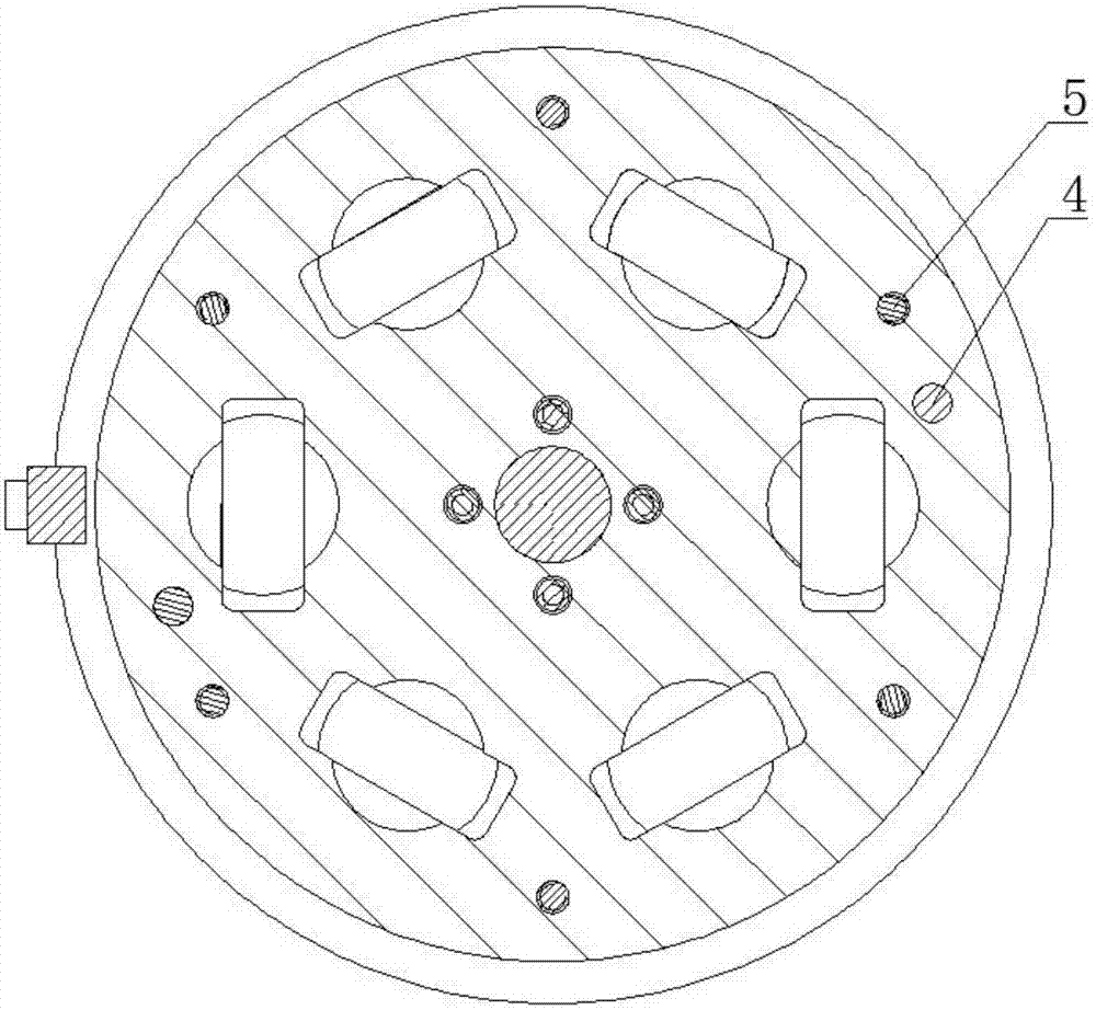
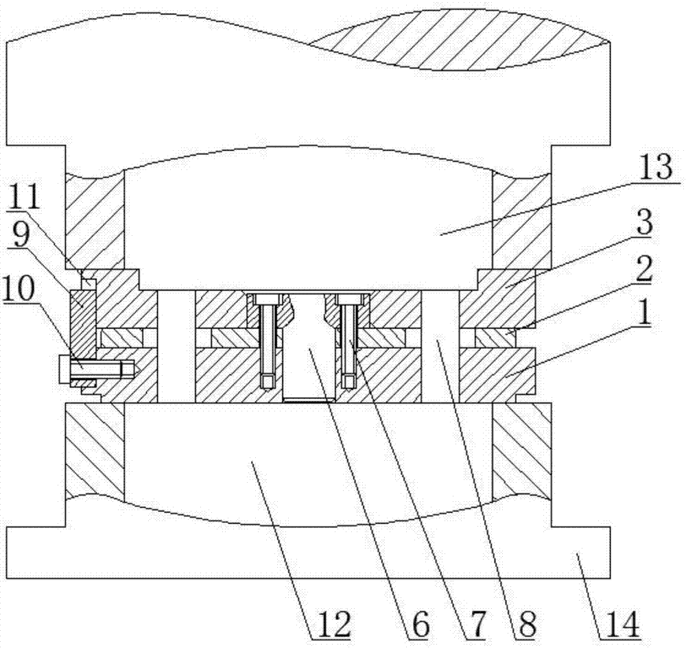
[0028] The invention provides a machining fixture and a machining method for special-shaped through slots, such as figure 1 , figure 2 , Figure 4 As shown, the machining fixture includes a chassis 1, a positioning disk 2, and a cover 3. The positioning disk 2 is connected to the upper end surface of the chassis 1 using a screw A4 and a positioning pin 5. The central axis of the chassis 1 is provided with a mandrel 6 and the upper end surface of the positioning disk 2 A groove 21 is provided, the cover plate 3 is sleeved on the mandrel 6, the cover plate 3 is connected with the chassis 1 through the positioning plate 2 with a screw B7, and the fixture is provided with a penetrating chassis 1, a positioning plate 2 and a cover plate 3 The abrasive through hole 8. Using the technical s...


PUM

PropertyMeasurementUnit
Diameteraaaaaaaaaa

Abstract

The invention relates to a machining fixture of an irregularly-shaped straight slot and a machining method. The machining method includes the steps that firstly a large part of allowances of the irregularly-shaped straight slot are removed by using a wire-cut machining method, and the machining allowance of the irregularly-shaped straight slot is reserved to be 0.01mm to 0.05 mm; parts of the irregularly-shaped straight slot are clamped on the fixture; once again the parts of the irregularly-shaped straight slot and the fixture are integrally mounted on an abrasive flow machine tool, the rest of the machining allowances of the irregularly-shaped straight slot are removed by using an abrasive flow machining mode; and finally the parts of the irregularly-shaped straight slot are dismounted from the fixture and the abrasive flow machine tool, the parts of the irregularly-shaped straight slot are inspected and put in storage after being washed. By using the technical scheme provided by the machining method, the machining method by combining fast wire cut with abrasive flow grinding machining together is used, firstly the large part of machining allowances are removed through fast wire cut , rough machining and forming are conducted, and then forming is completed through the abrasive medium grinding mode, so that the roughness of the surface around the irregularly-shaped straight slot is improved greatly, the machining cost is reduced, and the machining accuracy and the machining quality are improved.

Description

Technical field [0001] The invention relates to the technical field of mechanical processing, and in particular to a processing fixture and a processing method for a special-shaped through groove. Background technique [0002] At present, with the development of the manufacturing industry, many small parts with high machining accuracy requirements are widely used in the aerospace industry. Such parts often have some special uses, so some special shapes need to be designed and processed on such parts. Through grooves, when processing special-shaped through grooves on this type of parts, due to the design requirements for high machining accuracy, the surface roughness requirement is Ra1.6, which makes manufacturing and processing difficult. If conventional plunge milling, grinding, and milling are used Such machining methods are difficult to meet the requirements of machining accuracy. For example, when using a milling machining method, a special milling cutter is required for plun...

Claims


Application Information

Patent Timeline
IPC IPC(8): B23P23/00B24C9/00B24C1/00B23H7/08B23H11/00
CPCB23H7/08B23H11/003B23P23/00B24C1/00B24C9/00
Inventor 曹连群严萍周雨付志峰李井平晏超超
Owner GUIZHOU LIYANG INT MFG
Why Eureka
Try Eureka