Blade profile receiving hole structure for prewhirl cooling system

A cooling system and hole structure technology, applied in the cooling of the engine, the cooling of the turbine/propulsion device, the engine components, etc., can solve the problem that the flow coefficient of the downstream blade air supply holes is reduced, the flow loss is large, the flow coefficient is low, and the temperature drop of the pre-swirl system. The problem of deterioration of characteristics, etc., can achieve the effect of increasing nozzle pressure ratio, reducing flow loss and reducing flow loss.

Inactive Publication Date: 2017-11-03
NORTHWESTERN POLYTECHNICAL UNIV
View PDF5 Cites 10 Cited by
  • Summary
  • Abstract
  • Description
  • Claims
  • Application Information

AI Technical Summary

Problems solved by technology

This axial through hole not only has a large flow loss and a low flow coefficient, but also reduces the flow coefficient of the air supply hole of the downstream blade.
This makes the temperature drop characteristics of the pre-rotation system worse and the power consumption increases

Method used


Image

  • Blade profile receiving hole structure for prewhirl cooling system
  • Blade profile receiving hole structure for prewhirl cooling system
  • Blade profile receiving hole structure for prewhirl cooling system

Examples


Embodiment 1

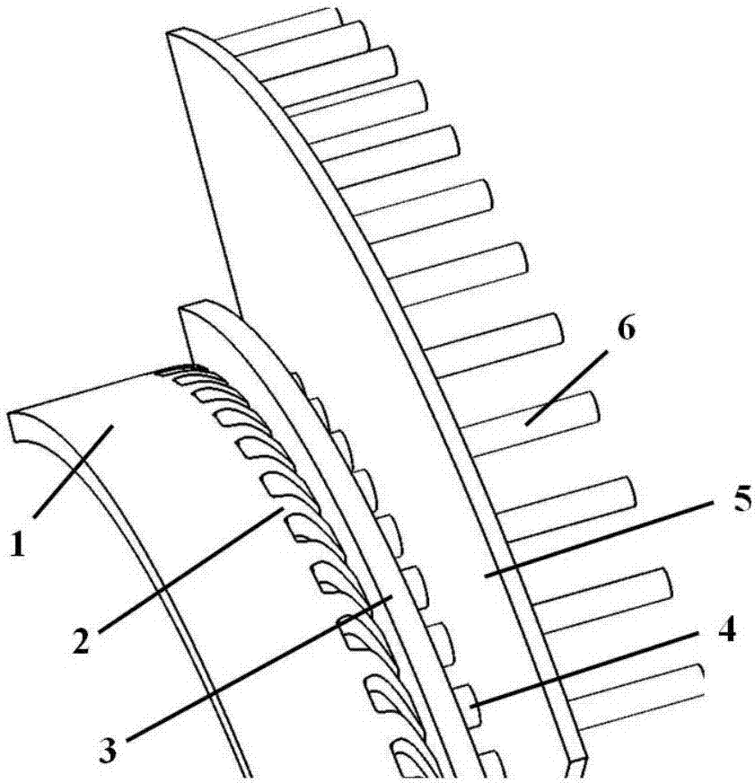
[0026] Example 1: figure 1 For the pre-rotation system structure. The pre-swirl system is composed of the air inlet chamber 1, the pre-swirl nozzle 2, the pre-swirl chamber 3, the receiving hole 4, the cover plate chamber 5 and the blade air supply hole 6. In the pre-rotation system, the inlet pressure of the air intake chamber 1 is the bleed air pressure of a certain stage of the compressor, which is basically a constant value; the outlet of the pre-rotation system is the blade air supply hole 6, and its pressure is basically a constant value. The air intake chamber 1 and the pre-rotating nozzle 2 are stationary parts, the receiving hole 4 and the blade air supply hole 6 are rotating parts; the pre-rotating chamber 3 is a rotary-static system, and the cover cavity 5 is a rotary-rotary system. The air inlet cavity 1, the pre-rotating nozzle 2, and the receiving hole 3 have the same radial position, and the air flow flows radially outward in the cover plate cavity 5 and flows ...

Embodiment 2

[0030]Embodiment 2: For a certain type of low-level cover plate type pre-rotation system, comparative analysis of the performance difference between the traditional axial straight-through receiving hole and the airfoil receiving hole; the geometric parameters of the pre-rotation system are shown in the following table.

[0031]

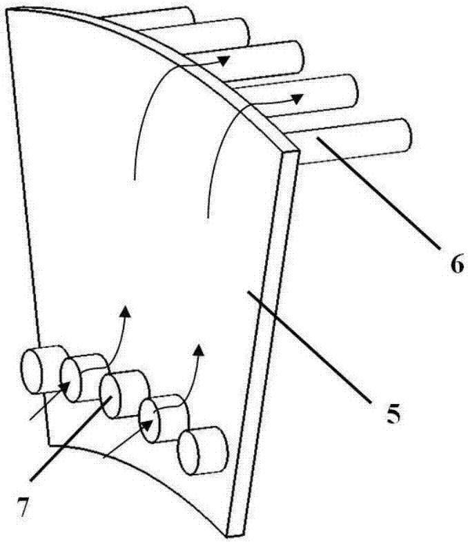
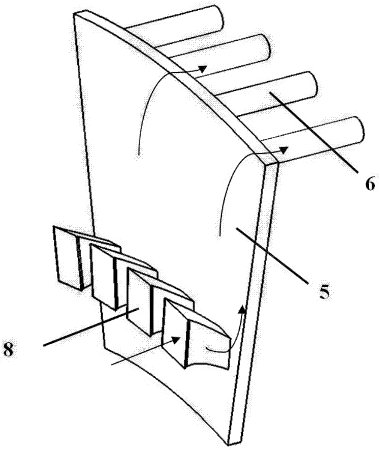
[0032] According to the CFD numerical simulation, the velocity streamline diagram of the axial straight-through receiving hole and the velocity streamline diagram of the airfoil receiving hole can be obtained. From Figure 7 It can be seen from the figure that the inlet of the axial straight-through receiving hole hinders the airflow, and an obvious vortex will be generated near the leeward side of the receiving hole, which will increase the flow loss inside the receiving hole and lead to a decrease in the flow coefficient. In the airfoil receiving hole, the proper air intake angle enables the air flow to flow into the receiving hole smoothly, and ...


PUM


Abstract

The invention discloses a blade profile receiving hole structure for a prewhirl cooling system. Each blade profile receiving hole is an inclined hole deflecting in the rotating direction of a rotary disc, a blade profile receiving hole runner is of a gradual contraction structure so that the effect that airflow is gradually accelerated in the axial flowing process. A blade profile receiving hole deflected profile comprises a self-designed blade profile force suction surface and a self-designed blade profile pressure surface and is used for ensuring the effect that the flowing loss of the airflow is the smallest when the airflow deflects along the blade profile receiving hole deflected profile. Each blade profile receiving hole has a blade profile receiving hole air inlet angle and a blade profile receiving hole air outlet angle which are determined by the nozzle outlet airflow rotating ratio and the receiving hole outlet target rotating ratio. The radial height, extending in the axial direction, of the blade profile receiving holes is gradually decreased. The acceleration characteristic of the blade profile receiving holes is ensured through blade profile receiving hole radial contraction curved surfaces on the two sides of the inlet section radial height and the outlet section radial height of the blade profile receiving holes. The flowing loss of the blade profile receiving holes and the flowing loss of air supply holes are decreased, so that the nozzle outlet rotating ratio is increased, the system temperature lowering seed is increased, and power consumption is reduced.

Description

technical field [0001] The invention relates to the application field of an aeroengine pre-swirl cooling system, in particular to an airfoil receiving hole structure used for the pre-swirl cooling system. Background technique [0002] As an important part of the aero-engine air system, the pre-swirl system (also known as the pre-swirl air supply system) plays the role of supplying cooling air to the high-speed rotating turbine rotor blades. A good pre-rotation system can reduce the temperature of the cold air by about 100K, and the huge temperature drop can greatly increase the operating safety of the aero-engine and prolong the working life of the engine. The main principle of pre-spin cooling is to accelerate the airflow through the pre-swirl nozzle and form a circumferential velocity component in the same direction as the turntable, reducing the static temperature of the airflow and the relative velocity between the turntable, so as to achieve the purpose of reducing the ...

Claims


Application Information

Patent Timeline
Patent Type & Authority Applications(China)
IPC IPC(8): F02C7/14
CPCF02C7/14
Inventor 刘育心刘高文孔晓治薛涵菲尚斌王掩刚
Owner NORTHWESTERN POLYTECHNICAL UNIV
Why Eureka
Try Eureka