Two-stage dual-dehumidification-evaporator and dual-dehumidification-condenser dehumidification heat pump system and method

A technology of evaporator and dehumidification heat, applied in evaporator/condenser, heating mode, air-conditioning system, etc., can solve the problems of unstable cycle performance, reduced adsorption and desorption capacity of desiccant, etc.

Active Publication Date: 2017-11-03
SHANGHAI JIAO TONG UNIV
View PDF4 Cites 14 Cited by
  • Summary
  • Abstract
  • Description
  • Claims
  • Application Information

AI Technical Summary

Problems solved by technology

However, when the desiccant on the surface of the desiccant is adsorbed and saturated, the low-temperature internal cooling source will cause condensation on the surface of the desiccant, and the liquid water produced will have a great adverse effect on the physical properties of the coated desiccant and subsequent regeneration. Instability and decline in the overall cycle performance
[0003] After searching the public literature of the prior art, it was found that in order to solve the above problems, Comfortable, high-efficiency heat pump with desiccant-coated, wa

Method used


Image

  • Two-stage dual-dehumidification-evaporator and dual-dehumidification-condenser dehumidification heat pump system and method
  • Two-stage dual-dehumidification-evaporator and dual-dehumidification-condenser dehumidification heat pump system and method
  • Two-stage dual-dehumidification-evaporator and dual-dehumidification-condenser dehumidification heat pump system and method

Examples


Embodiment Construction

[0098] The present invention will be described in detail below in conjunction with specific embodiments. The following examples will help those skilled in the art to further understand the present invention, but do not limit the present invention in any form. It should be noted that those skilled in the art can make several changes and improvements without departing from the concept of the present invention. These all belong to the protection scope of the present invention.

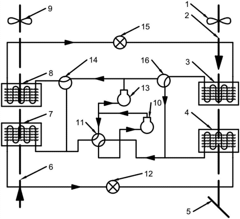
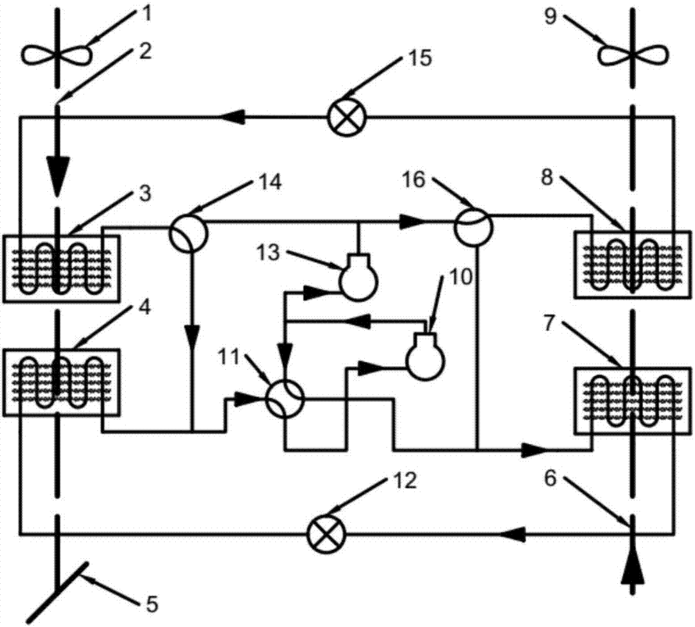
[0099] In the present invention, two dehumidification evaporators / condensers connected in parallel at different evaporation / condensation temperatures are used, and the treated air flows through the high-temperature and low-temperature dehumidification evaporators in sequence. The high-temperature dehumidification evaporator focuses on using a desiccant with uniform adsorption speed to achieve heat and humidity load pretreatment, prevents self-condensation through high evaporation temperature, and reduces...


PUM


Abstract

The invention provides a two-stage dual-dehumidification-evaporator and dual-dehumidification-condenser dehumidification heat pump system which comprises a closed refrigerating fluid system. The closed refrigerating fluid system comprises a low-temperature-side compressor, a four-way reversing valve, a first low-temperature-side dehumidification heat exchanger, a second low-temperature-side dehumidification heat exchanger, a low-temperature-side throttle device, a high-temperature-side compressor, a first three-way reversing valve, a second three-way reversing valve a high-temperature-side throttle device, a first high-temperature-side dehumidification heat exchanger and a second high-temperature-side dehumidification heat exchanger. The invention further provides a two-stage dual-humidification temperature increase and decrease method. In the system and the method, the two dehumidification evaporators/condensers connected in parallel at different evaporation/condensation temperatures are adopted, and treatment air sequentially flows through the high-temperature dehumidification evaporator and the low-temperature dehumidification evaporator. Compared with the prior art, according to the system and the method, the circulating switching time is prolonged, reliability and economic performance are both improved to a certain degree, and in addition, multi-mode operating can be achieved through switching.

Description

technical field [0001] The invention relates to a system in the field of solid dehumidification air-conditioning heat pump technology, in particular to a two-stage dehumidification heat pump system with double dehumidification evaporators and double dehumidification condensers. Background technique [0002] Decoupling solid dehumidification air-conditioning technology uses desiccant to deal with the latent heat load in the air, while the sensible heat load is dealt with by natural cold source or traditional compression refrigeration system. The system realizes the separate processing and independent control of sensible heat load and latent heat load. It overcomes the limitation of centralized processing load of compression air-conditioning technology. However, the heat of adsorption released by the dehumidification material during the solid dehumidification process will not only increase the sensible heat load to be treated in the follow-up, but also cause an increase in the...

Claims


Application Information

Patent Timeline
IPC IPC(8): F24F5/00F25B13/00F25D21/14F25B39/00
CPCF24F5/001F25B13/00F25B39/00F25D21/14
Inventor 葛天舒陆繁莉代彦军王如竹
Owner SHANGHAI JIAO TONG UNIV
Why Eureka
Try Eureka