Optical film visual intelligent detection equipment

A detection equipment and visual intelligence technology, applied in the direction of optical testing flaws/defects, material analysis by optical means, measuring devices, etc., can solve the problems of missed inspection, high labor cost, product waste and other problems

Active Publication Date: 2017-11-03
苏州市朗电机器人有限公司
View PDF5 Cites 9 Cited by
  • Summary
  • Abstract
  • Description
  • Claims
  • Application Information

AI Technical Summary

Problems solved by technology

[0004] 1. Completely manual inspection, through the human eyes of the inspectors to observe the brightness enhancement film products, to find defective brightness enhancement films and eliminate them; this manual inspection method leads to high labor costs for enterprises, and the detection efficiency is not good; the actual In addition, human eye detection is also prone to fatigue and missed detection, so there is still a problem of low reliability, resulting in unstable product quality;
[0005] 2. Mechanical testing, which intends to replace manual testing with automated testing equipment; however, looking at the industry, there is no well-designed solution. Existing testing equipment or mechanisms are too complex, there are too many redundant structures, or the testing efficiency is not good. , low reliability; in addition, since the brightness enhancement film products are usually arranged on the belt-shaped base film at intervals during testing, and are covered by a belt-shaped protective film, when testing, the equipment often misses due to the cover of the protective film. Defects in the brightness enhancement film itself, sometimes mistakenly identify and eliminate defects on the protective film as defects of the brightness enhancement film, resulting in false detection and waste of products

Method used


Image

  • Optical film visual intelligent detection equipment
  • Optical film visual intelligent detection equipment
  • Optical film visual intelligent detection equipment

Examples


Embodiment

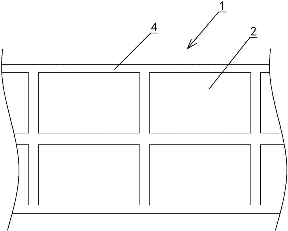
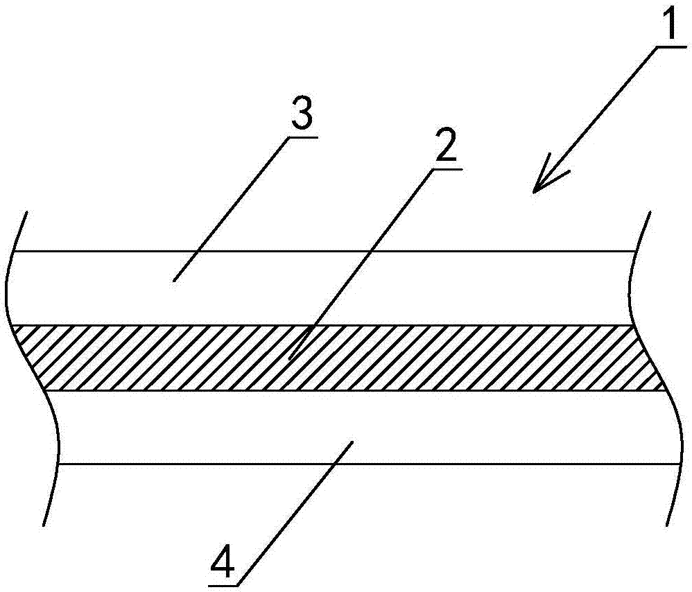
[0086] Example: see attached Figure 1-16 As shown, an optical film vision intelligent detection device is used to detect the optical film product 2 in the optical film material belt 1, and the optical film material belt 1 is composed of a protective film 3, an optical film product 2 and a base film 4 from top to bottom The following combination (such as figure 1 , 2 ).

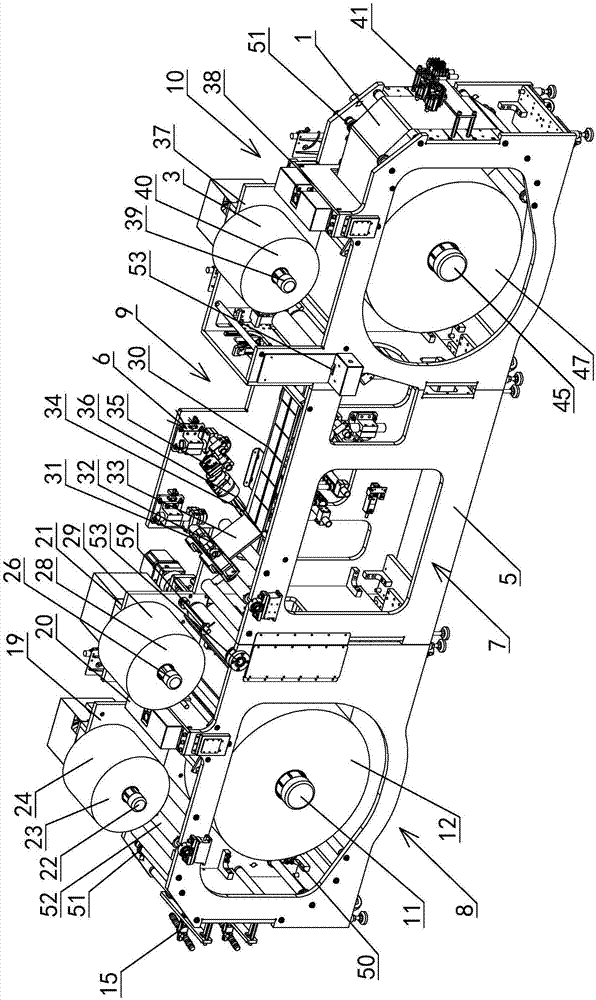
[0087] Described detection equipment comprises a frame 5, and the length direction of this frame 5 is the X-axis direction, and the width direction of frame 5 is the Y-axis direction; Displaced backward, the frame 5 is divided into an upper space 6 and a lower space 7 in the Z-axis direction based on the optical film strip 1;

[0088] The detection equipment also includes a feeding unit 8, a detection unit 9 and a receiving unit 10 arranged in the frame 5 from front to back along the X-axis direction; wherein,

[0089] like Figure 6~8 As shown, the feeding unit 8 includes:

[0090] A feeding module, lo...


PUM


Abstract

Optical film visual intelligent detection equipment comprises a feeding unit, a detection unit and a collection unit; the feeding unit comprises a feeding module and a protection film uncovering mechanism, the protection film uncovering mechanism comprises an adhesive tape feeding module, an adhesive tape pressing and attaching module and a protection film uncovering module; the detection unit comprises a lighting module, a camera shooting module and an upper computer; the collection unit comprises a protection film attaching mechanism, a defective-product marking mechanism and a collection module, and the protection film attaching mechanism comprises a protection film feeding module and a protection film pressing and attaching module. The optical film visual intelligent detection equipment is mainly used for full-automatically detecting optical film products in a visual intelligent detection way to further screen out defected optical film products, and has the advantages of high detection efficiency, high detection reliability; meanwhile, because of relatively reasonable structure design, the advantages of compact structure, small occupied area and relatively low cost are achieved; above all, not only is the defect identification rate of the equipment to the optical film products high, but also false detection cannot occur, so that the quality control of the products is ensured.

Description

technical field [0001] The invention relates to a detection device, in particular to a visual intelligent detection device of an optical film, and the optical film includes a brightness enhancement film, a protective film, etc. used in a mobile phone or a tablet computer. Background technique [0002] With the continuous development and progress of science and technology, the market for electronic products, especially mobile intelligent terminal products, continues to expand, and a large demand for optical films has emerged as the times require. [0003] There are many kinds of optical film products, which are widely used in mobile intelligent terminal products, among which brightness enhancement film is a typical example. Brightness Enhancement Film (BEF, Brightness Enhancement Film) is a film or sheet used in TFT and LCD backlight modules to improve the luminous efficiency of the entire backlight system of electronic equipment. It is widely used in liquid crystal displays....

Claims


Application Information

Patent Timeline
Patent Type & Authority Applications(China)
IPC IPC(8): G01N21/95G01N21/958G01N21/88G01N21/84G01N21/55G01N35/10
CPCG01N21/55G01N21/8422G01N21/8851G01N21/95G01N21/958G01N35/10G01N2021/8438G01N2021/8455G01N2021/8887G01N2021/9511
Inventor 徐涛周永
Owner 苏州市朗电机器人有限公司
Why Eureka
Try Eureka